Assembly components of the right drive shaft
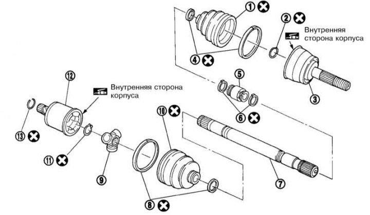
1, 10 - Anther; 2, 11, 13 - Retaining ring; 3, 12 - CV joint assembly; 4, 8 - Bandage tapes; 5 - Torsional vibration damper; 6 - Clamps; 7 - Drive shaft; 9 - Tripod joint
Disassembly
1. Remove the bandages.
2. Clamp the shaft in a soft metal vise and remove the circlip and inner CV joint housing.
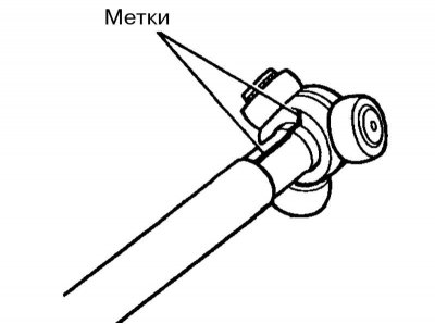
3. Paint marks on the shaft and tripod joint.
4. Remove the circlip and remove the tripod joint from the drive shaft.
5. Remove the boot from the shaft.
6. Remove the bandage tapes and slide the anther from the outer CV joint.
7. Remove the CV joint (see paragraph 9) and clean the hinge cage with paper towels from the old grease. Check up a condition of the hinge and if necessary replace it.
8. Remove the dust boot and circlip from the drive shaft
9. If necessary, remove the torsional vibration damper from the right drive shaft, having previously removed its clamps.
Assembly
1. To assemble the shaft on the wheel side, proceed in accordance with paragraphs 13 to 20.
2. Wrap tape around the transmission side of the shaft spline to prevent damage to the dust boot when it is installed. Install on the shaft new anther and new anther bandage tapes.
3. Remove the protective tape and install the tripod garnish on the drive shaft, aligning the marks made during removal.
4. Secure the tripod garnish with a new retaining ring.
5. Stuff the tripod garnish with grease and install the shroud on it.
6. Pack 115±5 g of lubricant into the casing.
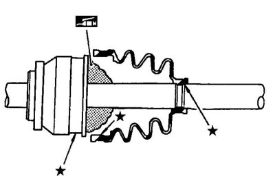
7. Install the boot securely into the grooves (* on illustration), having previously removed the grease from the surfaces marked with *.
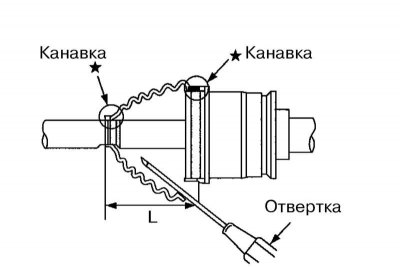
8. Make sure the boot length is (L) is 96.5±1mm. Pry off the edge with a screwdriver (from the larger diameter side) the dust boot and bleed the air out of it to prevent the dust boot from deforming.
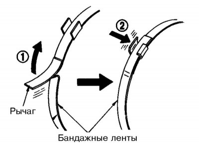
9. Fix the boot of the inner CV joint new bandage tapes in accordance with the illustration.
Note. Turning the CV joint, make sure that the position of the anther does not change. Otherwise, install a new boot.
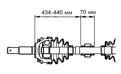
10. If the vibration damper was removed, install it in accordance with the illustration.