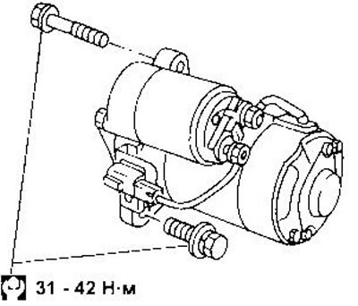
Removal and installation
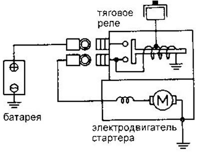
Switching scheme
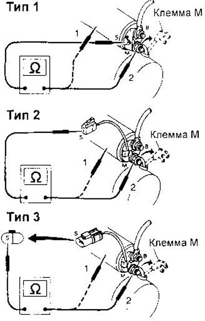
Examination
Traction relay. Before starting the test, disconnect the ground wire from the battery. Disconnect the M terminal of the starter motor. Check for continuity between terminal 8 and housing and between terminals 8 and M.
Drive gear and overrunning clutch. Check the condition of the gear teeth. If they are broken, damaged, or worn, replace the gear. (At the same time, check the condition of the flywheel ring gear.) The drive gear should rotate freely in one direction and lock in the other. Bel gg she spins (or not spinning) in both directions, or if there is unusual resistance, replace the freewheel.
Also check the condition of the gears (sat down it is present in the design of the starter).
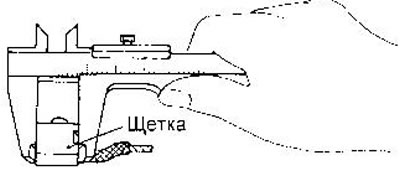
Motor brushes. Measure the remaining length of the brushes. The minimum allowable length is given in the subsection «Data for adjustments and control».
Brush springs. Check the clamping force with a dynamometer (with new brushes). Permissible values are given in subsection «Data for adjustments and control».
brush holder. 11Check the insulation resistance between the brush cages and the base. If there is continuity, replace the brush holder. Check the ease of movement of the brushes in the clips. If necessary, clean the sliding surfaces. Replace bent brush holder.
stator. Check if the magnets are secure (which are glued to the stator) and whether they have any cracks. Replace the stator assembly if necessary. The holders may move slightly as they are simply inserted and not glued.
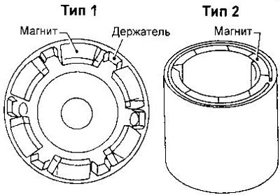
Do not press the stator into a vise or hit it with a hammer.
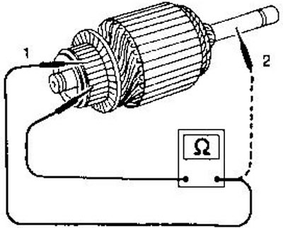
Anchor. Check the resistance between each pair of adjacent collector fins. If there are breaks, replace the anchor. Check the insulation resistance between each of the blades and the armature shaft. If there are short circuits, replace the armature.
If the collector surface is scratched, burned, or dirty, sand the collector with 500-600 grit sandpaper.
Measure the collector diameter. The minimum allowable diameter is given in subsection «Data for adjustments and control».
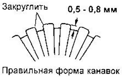
Check the depth of the grooves between the lamellas. If it is less than 0.2 mm, cut the grooves with a needle file to a depth of 0.5-0.8 mm.
Assembly
Lubricate bearings, gears and friction surfaces with high temperature grease when assembling.