2. Turn away nuts and get an adjusting bolt (photo).
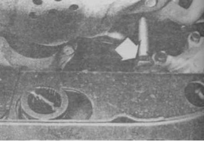
5.2 Torsion bar adjusting bolt nut (on all-wheel drive vehicles)
3. Remove the cover and remove the retaining ring (photo).
5.3 Cover and retaining ring of the torsion arm
1. Case; 2. Retaining ring
4. On rear-wheel drive vehicles, shift the torsion bar lever from the side of the body towards the rear of the car and remove the torsion bar. Remove the torsion arm from the lower suspension arm (photo).
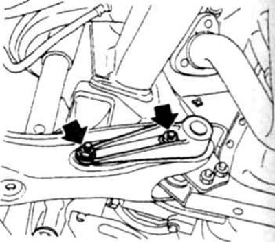
5.4 Nuts securing the torsion arm to the lower suspension arm on rear wheel drive vehicles
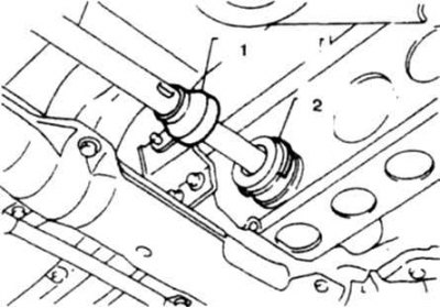
5. On all-wheel drive vehicles, remove the bolts securing the torsion bar to the lower arm (photo) and remove the torsion bar together with the inner arm, moving it towards the front of the car.
5.5 Nuts securing the torsion arm to the lower suspension arm on four-wheel drive vehicles
6. Check the condition of the torsion bar, the presence of torsional deformations, damage, check the integrity of the splined endings.
7. On rear-wheel drive vehicles, attach the torsion arm to the lower arm, tighten the bolts to the specified torque. Lubricate the splines and insert the torsion bar into the arm from the suspension side.
8. On four-wheel drive vehicles, attach the torsion bar to the lower arm and tighten the bolts to the specified torque.
Attention! If both torsion bars were removed, then install them in their original places, guided by the marks R (right) and L (left).
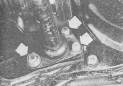
9. Jack up the lower arm until the buffer of the arm rests against the frame (photo).
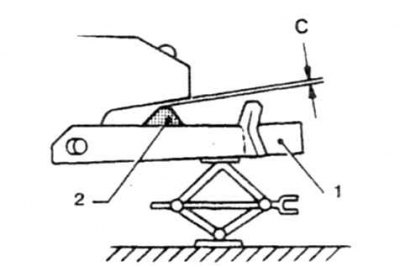
5.9 Before installing the torsion bar, clearance C must be equal to 0.
1. Lower arm; 2. Buffer
10. Install the fixed arm and adjust the initial position of the movable torsion arm so that the gap G corresponds to that specified in Technical Data (photo).
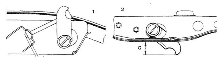
5.10 Install the fixed torsion arm on the frame side and adjust so that clearance G is correct
1. On rear-wheel drive vehicles; 2. On all-wheel drive vehicles
11. Install the retaining ring in the groove of the movable arm and put on the cover.
12. Turning the nut of the fixed arm, set the dimension L of the protrusion of the bolt (photo).
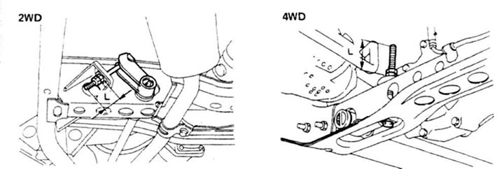
5.12 Turning the nut, set the protrusion dimension L of the fixed arm bolt
1. On rear-wheel drive vehicles; 2. On all-wheel drive vehicles
13. Lower the car onto the wheels and crimp the suspension. Check the swing amplitude of the lever H at the indicated points (photo). If the size H does not correspond to that specified in the Technical Data, then turn the nut of the torsion bar bolt to set the standard size.
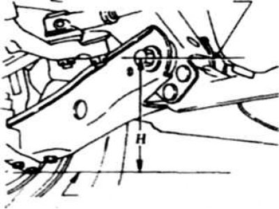
5.13a Dimension H, which should be set when adjusting the torsion bar on rear-wheel drive vehicles
1. The center of the axle of the lower suspension arm; 2. Bot fastening stretch marks
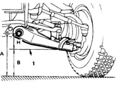
5.13b Dimension H, which should be set on all-wheel drive vehicles
1. Lower edge of slew limiter
14. Check and adjust wheel alignment (carried out in a car service).