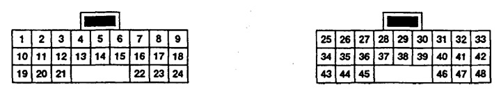
Standard input/output voltages of the ADS control unit
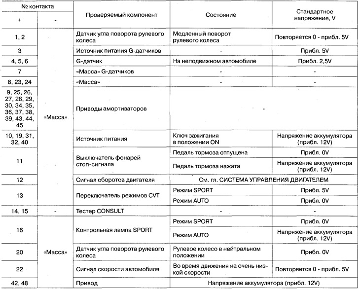
Component Check
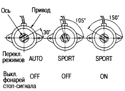
Automatic transmission mode switch
Disconnect the wiring connector from the switch, check the continuity between contacts 1 and 2 of the switch.
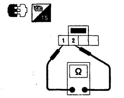
- In AUTO mode: conduction present
- In SPORT mode: no conduction
Shock absorber drives
Disconnect the wiring connector from the actuator and measure the resistance between the actuator terminals.
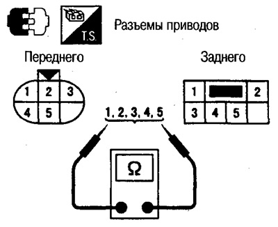
Front drives: Pins 1,2, 4, 5 - 3: approx. 12 Σ
Rear drives:
- Contacts 1-2: 0 Σ
- Pins 3-2: Approx. 22 Σ
- Pins 4-2: Approx. 12 Σ
- Pins 5-2: Approx. 22 Σ
Health check
Remove the drive assembly from the rack assembly and inspect as shown.
Removing and installing components
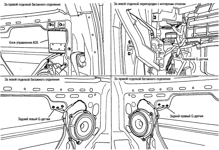
G-sensors
Preparatory work:
Before removing the front sensor, remove the glove box, left engine bulkhead trim, and ECCS unit.
Before removing the rear sensor, remove the luggage compartment trim.
ADS control unit
Preparatory work:
Before removing the control unit, remove the right luggage compartment trim.