Removing
1. Remove a rotary fist from the cross-section lever, see above.
2. Remove the stabilizer bar connecting rod bracket from the transverse arm.
3. Loosen the transverse arm and pin mounting nuts and unscrew the pin mounting bolt.
4. Turn off a nut of fastening of the cross-section lever and a finger, remove a finger from the lever.
5. Turn off fixing bolts of the cross-section lever and remove it from the car.
Examination
Check for deformation, cracks or other damage on the transverse arm and bushings. If necessary, replace the transverse arm assembly.
Check for any deformation, cracks or other damage on the finger. Replace if necessary.
Ball joints
Caution: Move the ball joint by hand at least ten times before taking a measurement to make sure it moves freely.
Vibrational moment
Hook the dynamometer to the mounting hole for the cotter pin. Check that the value measured by the dynamometer is within the normal range when the ball joint tip starts to move.
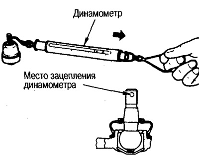
- Vibrating moment: 0.50-4.90 Nm (0.05-0.50 kgm)
- Dynamometer reading: 7.90-77.4 N (0.80-7.90 kg)
If the measurement is out of specification, replace the control arm.
slip moment
Thread the retaining nut onto the ball joint head and use a preload gauge to verify that the sliding torque is within specification.
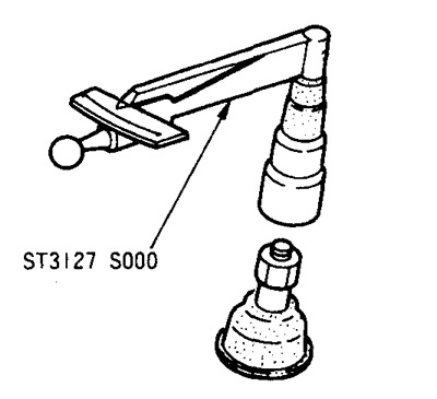
- Sliding torque: 0.50-4.90 Nm (0.05-0.50 kgm)
If the measurement is out of specification, replace the control arm.
Axial play
Move the tip of the ball joint in the axial direction and check the play.
Axial play: 0 mm
If there is play, replace the transverse link.
Installation
Installation is carried out in the reverse order of removal.