


Table of contents: Examination ↓ Assembly ↓
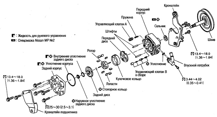
1. Clamp the pump in a vice.
Caution: When clamping in a vice, place aluminum plates, etc. between the clamps to prevent damage to the pump.
2. Unscrew the 2 bracket mounting bolts from the front housing side. Remove the bracket.
3. Unscrew the 3 bracket mounting bolts from the front housing side and remove the bracket.
4. Unscrew the 4 mounting bolts of the rear housing and remove it from the front housing.
5. Remove the seal from the front housing.
6. Remove the rear disc from the cam ring, remove the inner and outer seals from the disc.
7. Using pliers, remove the rotor retaining ring and remove the pulley from the front housing.
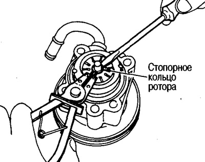
Caution: Be careful not to damage the pulley shaft when removing the snap ring.
8. Remove the cam ring, rotor and blades, front disc, control valve A, its spring and control valve B assembly from the front housing.
Caution: Do not drop the control valves to prevent them from becoming deformed.
9. Unscrew the inlet pipe mounting bolt and remove the pipe from the front housing.
10. Remove the seal from the inlet pipe.
11. Using a screwdriver or other tool, remove the drive shaft seal from the front housing.
Caution: Do not damage the surface of the front case.
Examination
Front and rear housings
Check the internal surfaces of the housings for deviations from the norm and damage. If there is damage in the rear housing, replace it, in the front housing - replace the pump assembly.
Cam ring
Check the cam ring for abnormalities and damage. Replace the cam ring, rotor and blades as a set.
Front and rear discs
Check the discs for any abnormalities or damage. Replace the front and rear discs as a set.
Assembly
1. Apply special Nissan MP No.2 grease to the edges of the drive shaft seal and, using a drift, (special tool) install the oil seal into the front housing.
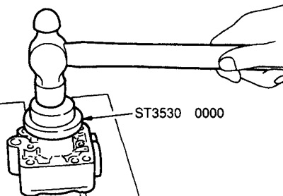
Caution: Do not reuse the oil seal, replace it with a new one.
2. If the pins have been removed, insert them into the front housing by hand and tap them into place with a hammer.
3. Install the control valve A and its spring, and the control valve B assembly as shown in the figure.
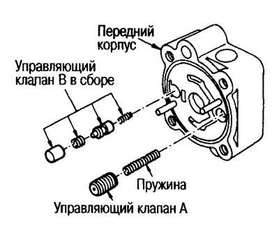
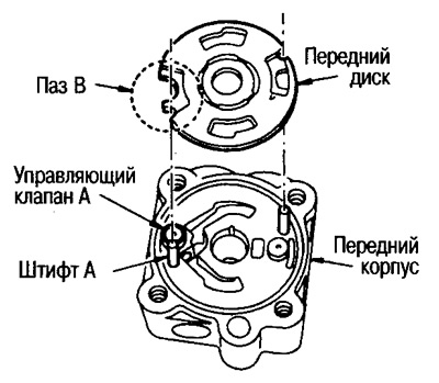
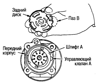
4. Align groove B with control valve A and pin A as shown in the figure and install the front disc to the front housing.
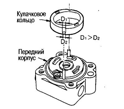
5. Position the cam ring so that the narrower part of the groove faces the front housing and install the cam ring onto the front disc.
6. Install the pulley onto the front housing.
Caution: Be careful not to damage the drive shaft seal.
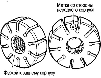
7. Install the rotor on the pulley shaft so that the mark faces the front housing.
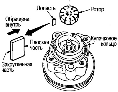
8. Install the blades with the rounded part away from the rotor.
9. Using a hammer and a 10mm punch, install the snap ring into the groove of the pulley shaft.
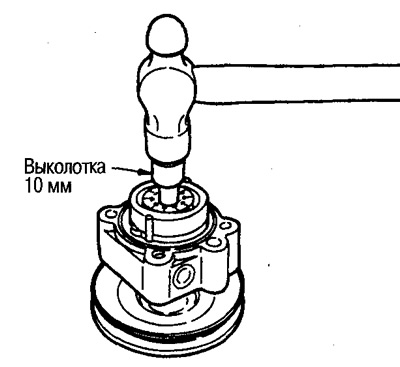
Attention:
Do not reuse the retaining ring, replace it with a new one.
Be careful not to damage the rotor or pulley shaft.
If the rotor is damaged, replace the power steering pump assembly.
10. Align groove B with control valve A and pin A as shown in the figure and install the rear disc on the cam ring.
11. Lubricate the housing seal with power steering fluid and install it into the front housing.
Caution: Do not reuse the housing seal, replace it with a new one.
12. Lubricate the inner and outer rear disc seals with power steering fluid and install them into the rear disc.
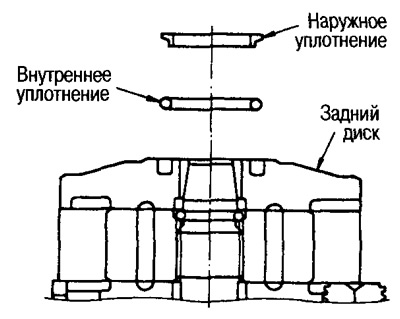
Caution: Do not reuse seals, replace them with new ones.
13. Clamp the pump in a vice.
Caution: When clamping in a vice, place aluminum plates, etc. between the clamps to prevent damage to the pump.
14. Install the rear housing onto the front housing, tighten the four mounting bolts diagonally to the required torque.
15. Install the bracket on the rear housing side and tighten the two mounting bolts to the required torque.
(Original text on the website: NISSANBOOK.ru)
16. Install the bracket on the front housing side, tighten the three mounting bolts to the required torque.
17. Insert the seal into the groove of the inlet pipe, install the pipe on the front housing and tighten the pipe mounting bolt to the required torque.
Caution: Do not reuse the hose seal, replace it with a new one.