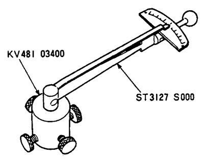
Attention: Do not reuse O-rings, replace them with new ones.
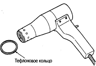
2. Using a hair dryer, heat the Teflon ring to a temperature of 40°and install it on the rail.
Attention: Do not reuse the Teflon ring, replace it with a new one.
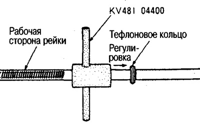
3. Place the special tool on the working side of the rail and adjust the position of the ring. Then squeeze the outer surface of the ring.
4. Install the rail glands.
Attention: Do not reuse seals, replace them with new ones.
(1) Wrap around the rail flange to prevent damage to the rail (approx. 70x100mm) piece of polyethylene. Install the gland and put it on the rail, advancing simultaneously with a piece of polyethylene.
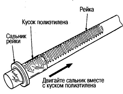
(2) Insert rack into steering gear housing assembly.
Attention: Do not damage or scratch the inner walls of the housing. Otherwise, oil leaks may occur, necessitating the replacement of the housing assembly.
(3) Install the centering sleeve on the rail.
Attention: Do not damage the inner walls of the housing with the rail. Otherwise, oil leaks may occur, necessitating the replacement of the housing assembly.
(4) Insert the inner seal onto the piston section, slide the rack into the body and install it so that the inner seal rests on the centering sleeve.
Attention: Do not damage the inner walls of the housing with the rail. Otherwise, oil leaks may occur, necessitating the replacement of the housing assembly.
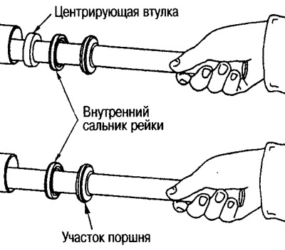
(5) Wrap around the rail flange to prevent damage to the rail (approx. 70x100mm) piece of polyethylene. Install the outer oil seal and push it onto the rail, advancing simultaneously with a piece of polyethylene.
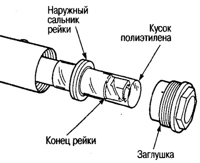
(6) Align the seals as shown in the illustration.
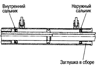
With a ring spanner, approx. 36 mm tighten the plug to the required torque.
Attention: Do not damage the rail surface. Otherwise, oil leaks are possible, which will necessitate the replacement of the rack.
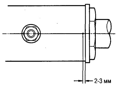
6. Tighten the cap. Then caulk the body as shown in the figure to prevent loosening.
7. Install shims and o-rings into the body.
Attention: Do not reuse shims, replace them with new ones.
8. Establish on the case the steering mechanism in gathering.
9. Install the lock plate on the rail.
(1) Put the spacer on the rail.
Attention: Do not reuse the spacer, replace it with a new one.
(2) Install the stop plate on the inner tip.
Attention: Do not reuse the lock plate, replace it with a new one.
(3) Apply a fixative (Three Bond 1324) on the thread of the inner lug, screw it into the rail and tighten with the required force.
(4) Caulk the locking plate into the slots on the rail in two places.
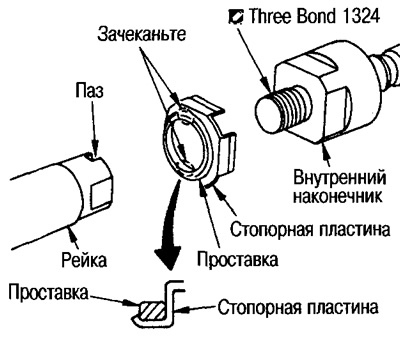
(5) Attach the spacer to the lock plate as shown.
Caution: Be careful not to damage the spacer.
10. Determine the neutral position of the rack.
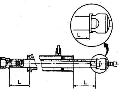
- Reiki travel «L»: 66.0 mm
11. Install the cap as shown.
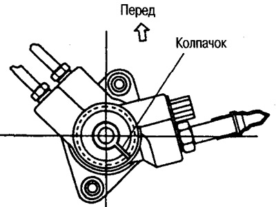
12. Install tubing on body.
13. Install the retainer and spring into the housing.
14. Apply Three Bond TB1111B to the threads of the adjusting screw and screw it in.
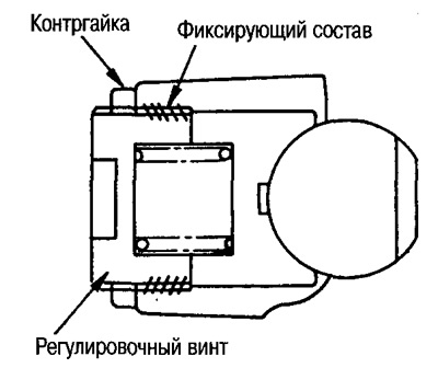
15. Tighten the locknut by hand without tightening it.
16. Tighten the adjusting screw to 4.9-5.8 Nm (0.5-0.6 kg m), then tighten by another 0.2 Nm (0.02 kg m).
17. Rotate the gear fully 10 times.
18. Using special tools, measure the rack turning force within±180". Stop at the point of greatest effort.
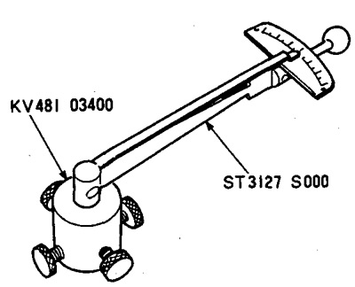
19. Loosen the adjusting screw. Then tighten it with a torque of 4.9 Nm (0.5 kg m) and tighten another 60-80°;
20. Fix the adjusting screw so that it does not turn and tighten the lock nut with a force of 40-58 Nm (4.0-6.0 kg m)
21. Install the indicator as shown. Turning the gear with a force of 20 Nm (0.2 kg m), measure the play of the rack and make sure that it is within the limits. If not, re-adjust. If, after re-adjustment, the measurement result is still abnormal, replace the steering gear.
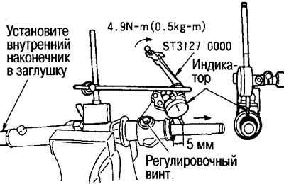
- Backlash measuring point: adjusting screw
- Rail play: 0.273 mm
22. Temporarily fasten the boot clamp on the large diameter side before installing the boot.
Attention: Do not reuse clamps, replace them with new ones.
23. Apply Nissan MP No. 2 special grease to the covers from the large and small diameters.
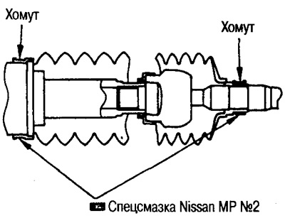
Attention: Do not reuse covers, replace them with new ones.
24. Install the boot with the small diameter side into the groove of the inner lug, secure the boot with a clamp from the small diameter side.
25. Secure the cover with a clamp on the side of the large diameter.
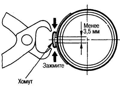
(1) Firmly fasten the clamp in the groove of the cover and clamp the attachment point with pliers.
(2) Clamp the attachment point so that the gap is less than 3.5 mm as shown in the figure.
(3) To avoid touching other parts, install the steering gear on the vehicle so that the mounting area is in the position shown in the figure.
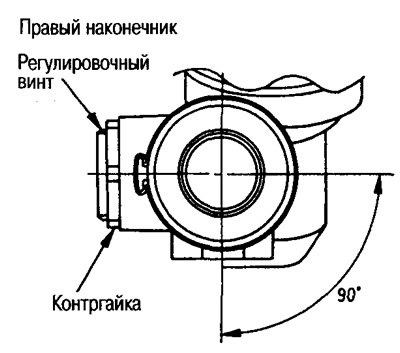
26. Install the locknut and outer tip on the inner tip. Tighten the locknut by hand to adjust the length of the tie rod.
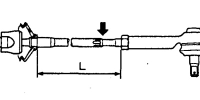
- Tie rod length L: 157.5 mm
Attention: After completing the work, adjust the toe. Length L after adjustment differs from above.
27. Establish the steering mechanism in gathering on the car, check up effort of turn of a lath.
Rack turning force
From the neutral position±11.5 mm, the amplifier works:
- Average force: 235.2-294.0 N (23.99-29.97 kg)
- Deviation: 117 N (12 kg) or less
Over the entire range of rack movement:
- Maximum force value (amplifier not working): 294 N (30 kg) or less
- Deviation: 147 N (15 kg) or less