Disassembly
Disassembly has no special features and is carried out in accordance with drawing.
Examination
Protective cases. Replace covers if cracked or torn.
Rack. Carefully check the condition of the rack. It must be replaced if damaged, cracked or visibly worn.
drive gear. Replace gear if damaged, cracked or worn. Check the ease of rotation of the bearings. Balls, rollers and treadmills must be free of cracks, pitting and visible wear. Replace bearings if necessary.
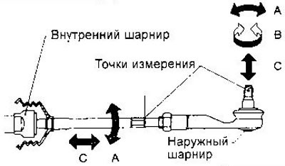
Inner and outer tie rod joints. Check the rolling resistance force (A) and axial clearance in ball joints (WITH). For an outer hinge, measure the torque resistance (IN). Control values are given in the section «Data for adjustments and control». If there are deep cracks and breaks on the protective covers of the outer hinges, replace the tie rod ends.
Assembly and adjustment
1. Insert the rack into the crankcase from the side of the drive gear and place it in the neutral position.
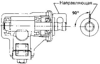
2. Insert the gear, then set the guide to the neutral position as shown in the figure. The rail must be held.
3. Install the rear cover using tool KV48102000.
Before installing the cover, apply a fixing compound to the threaded parts. Keep the compound away from the gear bearing.
Apply multipurpose grease to the sealing lip of the boot.
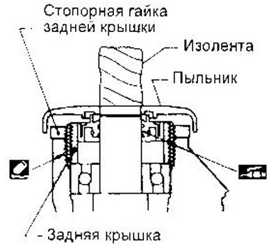
WARNING: When installing the boot, wrap the end of the gear with electrical tape.
4. Insert rack stop, spring, thrust washer and lock washer. Then tighten the adjusting screw, applying a locking compound to the threads.
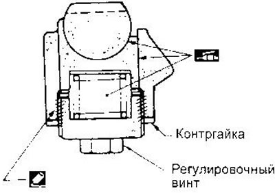
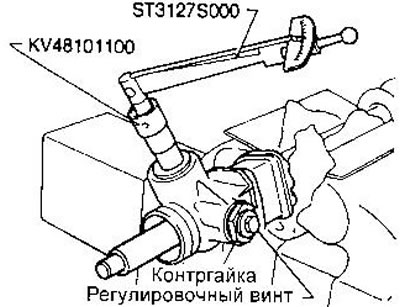
5. Adjust gear torque as follows.
Set the mechanism to neutral position and loosen the locknut. Tighten the adjusting screw with a torque of 9.8 Nm, then loosen it and tighten it again with the same torque.
Loosen the adjusting screw (within 60°), until the desired gear torque is reached. Check that at a torque of 1.5 Nm, the gap between the gear and the rack is no more than 0.1 mm.
While holding the adjusting screw, tighten the locknut to 39-59 Nm.
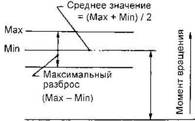
Slowly rotate the gear 100°from neutral to verify that the torque is within the following limits:
- Average torque - 0.7-1.2 Nm
- Maximum spread - 0.3 Nm
- Out of range = 100°:
- Maximum torque - 1.5 Nm
- Maximum spread - 0.5 Nm
If the gear torque is not within the specified limits, repeat the adjustment.
If the adjustment fails to set the desired torque, replace the stop spring.
If replacing the spring does not produce the desired result, replace the steering gear.
6. Burnished protective cover on the inner joint of the tie rod.
7. Put on a new lock washer 2 on the inner hinge 1 of the steering rod. Screw the hinge into rail 4 and tighten to the specified torque. Press the edge of the lock washer into the grooves on the rail.
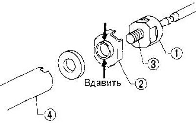
CAUTION: To avoid scratching the protective boot, remove all burrs from the lock washer.
8. Install the locknut and outer ball joint tip on the tie rod. Set the desired length L and tighten the locknut.
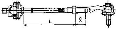
Tie rod length L is given in section «Data for adjustments and control».
- Screwed length (l) - not less than 32 mm
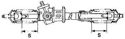
9. Measure the stroke of the rack S. Its value is given in the section «Data for adjustments and control».
10. Before installing the protective boot, apply grease to the contact surfaces of the boot and tie rod.
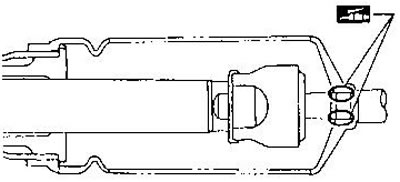
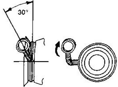
11. Secure the boot with a tie. To do this, wind the clamp around the groove of the cover twice and tighten it with a screwdriver.
Twist the rings 4-4.5 turns, pulling them with si about 98 N (10 kgf).
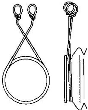
Do not cross the wire on the case itself.
Bend the twisted ends as shown (this will prevent them from coming into contact with other parts).