


Table of contents: Component arrangement (model R24T) ↓ Disassembly ↓ Checking after disassembly ↓ Assembly ↓
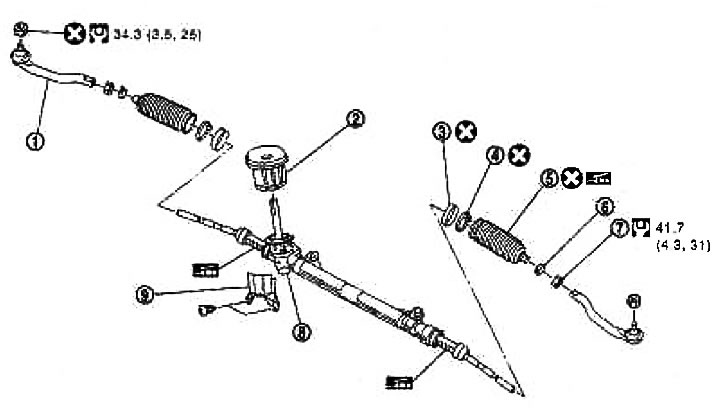
1. External tip; 2. Sealing the partition; 3. Sealing ring; 4. Clamp; 5. Cover; 6. Clamp; 7. Lock nut; 8. Steering gear assembly; 9. Heat shield
Component arrangement (model R24T)
Disassembly
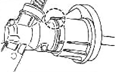
1. Disengage the bulkhead seal tab and remove it from the steering gear.
2. Loosen the outer tie rod end lock nut and remove it from the steering gear.
3. Remove the clamp and clip (cut off) and remove the boot and sealing ring.
Caution: When removing the boot, be careful not to damage the inner tip and the steering gear housing assembly.
Checking after disassembly
Rail
Check for wear and damage. Replace if necessary.
Partition sealing
If the tab breaks off or the seal is torn, replace it.
Tie rod end ball joint
1. The moment of swinging.
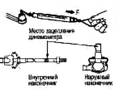
Hook the dynamometer as shown in the figure and pull it. Check that the reading at the moment the ball joint tip and the inner tie rod end begin to move is within the normal range. If the reading is not normal, replace the outer tie rod end and the steering gear assembly.
| Component | External tip | Inner tip |
| The location of the dynamometer engagement | Ball joint tip | Place of engagement |
| Swinging moment, Nm (kg-m) | 0,3-2,9 (0,03-0,29) | 0,5-5,0 (0,05-0,51) |
| Dynamometer measurement, N (kg) | 5-54 (0,51-5,51) | 4-43 (0,41-4,4) |
2. Axial play of ball joints.
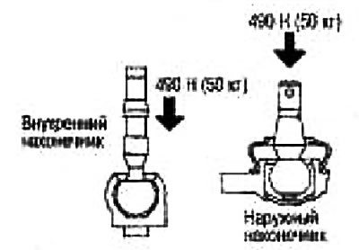
Apply a load of 490 N (50 kg) to the ball joint tip in the axial direction. Using a dial indicator, measure the amount of movement that the tip makes. Make sure that the reading is within the standard range specified below. If the value is not, replace the outer tip and the steering gear assembly.
| External tip | There is no play |
| Inner tip | There is no play |
3. Using a preload measuring device (special tool) measure the worm rotation torque. If the torque is different from the norm, replace the steering gear.
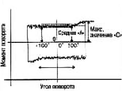
Worm rotation moment
Near neutral position (within ±100°): Average "A": 0.7-1.2 N·m (0.07-0.12 kg·m)
Other than above: Max value 1.6 N·m (0.16 kg·m)
Assembly
Assembly is carried out in the reverse order of disassembly, taking into account the following:
Apply general purpose grease to the sliding area of the rack.
Securely fasten the cover and the sealing ring with a clamp. Calibrate the clamp and cut off the excess.
Insert the bulkhead seal tab into the steering gear.
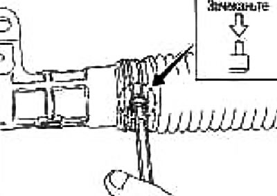
Screw the lock nut and place the outer end on the inner end and tighten the lock nut until the tie rod length is within the specified range (length before toe adjustment).
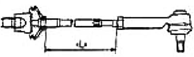
Length of steering rod, "L": 57.8 mm
Note: Perform toe adjustment after this procedure. The length obtained after toe adjustment does not necessarily have to be equal to the value given here.