


Table of contents: Components ↓ Electric Power Steering Operation ↓
Components
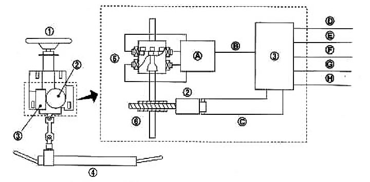
1. Steering wheel; 2. Electric motor; 3. EPS control unit; 4. Steering gear assembly; 5. Torque sensor; 6. Reducer; A. Sensor signal processing; B. Sensor signal; C. Torque Boost Signal (electric motor drive); D. Ignition system power supply; E. CAN communication line (H); F. CAN communication line (L); G. Power supply; H. Mass
Electric Power Steering Operation
| Component | Purpose |
| Electric Power Steering (EPS) Control Unit | Provides an optimal torque boost signal to the electric motor proportional to the steering wheel rotation force (sensor signal) from the torque sensor and from the vehicle speed signal from the CAN bus.
Reduces the amount of output signals to the electric motor and provides protection for the electric motor and EPS control unit during continuous and excessive use of the electric power steering. If a fault occurs in the electrical system, the emergency mode is activated, the output signal to the electric motor is interrupted and the steering is switched to manual mode. The EPS indicator lamp lights up, indicating a fault in the system. Manages the exchange of information with other control units via the CAN bus. Allows you to perform system diagnostics using the CONSULT-II software |
| Electric motor | Generates torque with amplification according to the signal from the EPS control unit. |
| Torque sensor | Detects the steering wheel rotation force and sends a signal to the EPS control unit. |
| Reducer | Amplifies the torque generated by the electric motor via a worm gear and transmits it to the steering shaft |
| EPS warning light | Lights up when the emergency mode is activated and indicates that the steering has been switched to manual mode.
Lights up when the ignition key is turned to the "ON" position to check the functionality and goes out after the engine starts. |