Head pressure sensor
1. The sensor is mounted on the left suspension cap.
2. Disconnect the battery from the ground.
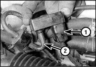
3. Loosen the screws lift the sensor and disconnect the hose (2) and connector (1), remove the sensor.
4. Installation is carried out in the reverse order.
Transistor module
See subsection 7.7.6.
Mixture Correction Valve
See subsection 6.1.10.2.
Solenoid valves
See subsection 6.1.10.2, pp. 18–26.
To expand the workplace, remove the air filter.
Throttle switch
Switch location
The throttle switch is mounted on the right side of the carburetor.
1. Remove two screws.
2. Disconnect the wires and remove the switch.
3. Adjust the switch when installing.
4. To adjust, warm up and stop the engine, disconnect the connector with the switch wires.
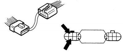
5. Connect jumpers between shut-off valve leads and connect an ohmmeter (the arrows indicate the leads for connecting an ohmmeter).
6. Start the engine, rev it up to 2000 rpm and slowly decrease, watching the ohmmeter, which should indicate a closed circuit, and at 1200 rpm an open (the switch is triggered).
7. If necessary, adjust the switch by bending the tab.
8. Stop the engine and connect the connector.
Coolant temperature sensor
See subsection 4.6.3.
Control block
The unit is mounted either under one of the front seats or under the center section of the front panel.
1. Disconnect the battery from the ground.
2. Remove the seat or center section.
3. Loosen the screws and remove the block, disconnect the wiring.
4. When installing, make sure all connections are correct.
Crank angle sensor
The sensor is included in the design of the ignition distributor and cannot be removed separately.
When the sensor fails, the entire distributor assembly is replaced (see subsection 7.7.4).
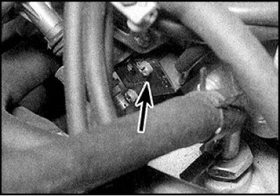
Clutch Release Sensor
Mounted on the pedal block bracket.
1. Disconnect the battery from the mass, remove the bottom panel.
2. Disconnect the wires, unscrew the nut and remove the switch.
3. When installing, check the clutch pedal adjustment and adjust the sensor.
4. To adjust, connect an ohmmeter to the sensor terminals and adjust the position so that when the pedal is released, there is a break, and when the pedal is slightly pressed, the circuit is closed.
5. Tighten the nut.
Transmission Neutral Position Sensor
See subsection 9.1.4.
Idling correction switch during hydraulic booster operation
The switch is built into the power steering circuit, in the right rear of the engine compartment.
1. Put the wheels in the straight ahead position and disconnect the battery from the ground.
2. Disconnect the connector from the switch.
3. Unscrew the switch and plug the hole in the tube, remove the seal.
4. When installing, replace the seal.
Vehicle speed sensor
The sensor is mounted in the speedometer.