


Removal
1. Raise the vehicle and remove the wheels.
2. Remove the nuts and bolts from the wishbone ball joint and remove the wishbone from the steering knuckle.
3. Remove the nuts and bolts from the wishbone and remove the wishbone from the suspension beam.
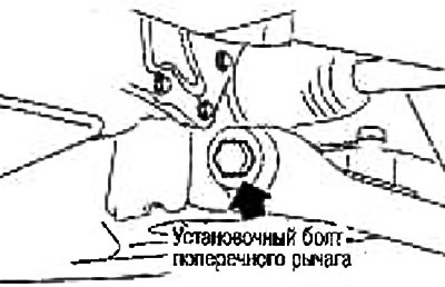
Note: When removing the left control arm (on models with automatic transmission) lower the suspension beam to remove the bolts to avoid contact and loosening the bolts at the front of the vehicle. Remove the suspension beam. See section "Front suspension beam".
- a. Place a jack under the suspension beam.
- b. Loosen the left control rod mounting bolt, the right control rod mounting bolt (from the suspension beam side), suspension beam mounting bolts (left/right). Lower the suspension beam to remove the wishbone mounting bolts.
Check after removal
Visual inspection
Check the wishbone and bushing for deformation, cracks or other damage. Replace if necessary.
Checking the ball joint
Move the ball joint end by hand and make sure it moves freely without binding.
Checking the swing moment
Caution: Before taking the measurement, move the ball joint tip by hand at least ten times to make sure it moves freely.
Attach the dynamometer to the cotter pin mounting hole. Make sure the value measured by the dynamometer is within the specified range when the ball joint tip begins to move.
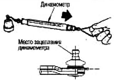
Swinging moment: 0.5-4.9 N·m (0.05-0.5 kg·m)
Dynamometer reading: 15.4-150.8 N (1.6-15.4 kg)
If the measured value is different from the standard, replace the control arm.
Checking axial play
Move the ball joint tip in the axial direction and check for play.
Axial play: 0 mm
If there is any play, replace the control arm assembly.
Installation
For tightening torques, see the Front Suspension Assembly section. Installation is the reverse order of removal.
Tighten the wishbone mounting bolts when the vehicle is unladen and the wheels are on level ground.
After installation, check the front wheel alignment angles. See section "Checking the front wheel alignment angles".