Disassembly
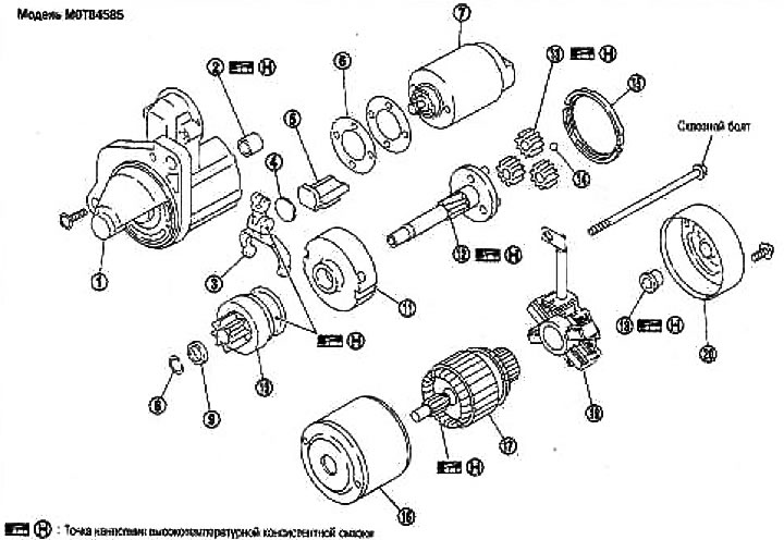
1. Gear housing; 2. Plain bearing; 3. Switching lever; 4. Plate; 5. Stuffing; 6. Adjusting washer; 7. Magnetic switch assembly; 8. Clip limiter; 9. Gear limiter; 10. Gear assembly; 11. Internal gear; 12. Gear shaft; 13. Planetary gear; 14. Ball; 15. Stuffing; 16. Stator; 17. Rotor; 10. Brush holder assembly; 19. Rear bearing; 20. Back cover
Through bolt: Model M0T84585
Tightening torque: 4.1-7.1 Nm (0.45-0.72 kg m)
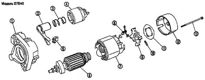
1. Gear housing; 2. Switching lever; 3. Spring; 4. Magnetic switch assembly; 5. Stuffing; 6. Rotor; 7. Stator; 8. Brush; 9. Brush holder assembly; 10. Spring; 11. Plate; 12. Back cover; 13. Through bolt
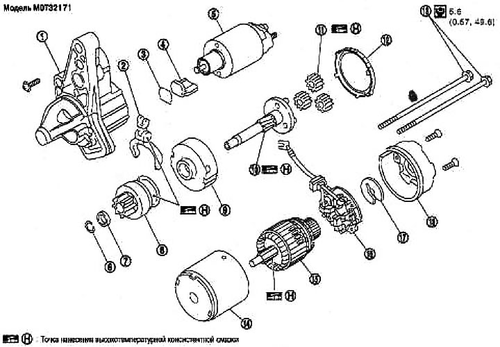
1. Gear housing; 2. Switching lever; 3. Plate; 4. Stuffing; 5. Magnetic switch assembly; 6. Ring; 7. Limiter; 8. Gear clutch assembly; 9. Internal gear assembly; 10. Gear shaft assembly; 11. Gear assembly; 12. Stuffing; 13. Through bolt; 14. Stator assembly; 15. Rotor; 16. Brush holder assembly; 17. E-ring; 18. Back cover assembly
Examination
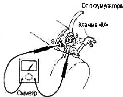
Checking the electromagnetic switch
Before testing, disconnect the ground cable from the battery.
Disconnect the terminal «M» starter.
1. Conductivity test (between terminal «S» and switch housing).
If there is no continuity, replace.
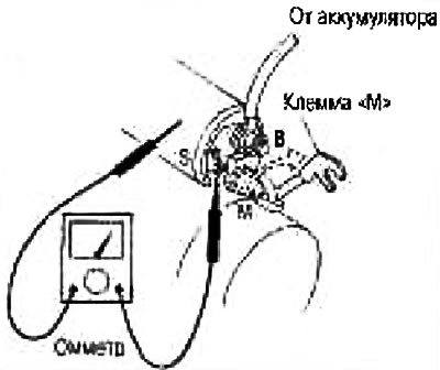
2. Conductivity test (between terminals «S» And «M»)
If there is no continuity, replace.
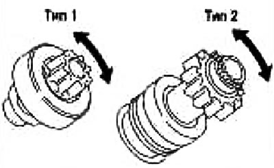
Checking the gear/clutch
1. Check the gear teeth.
Replace gear if teeth are worn or damaged (Also check the condition of the ring gear teeth).
2. Check gear teeth (if provided).
Replace gearbox if teeth are worn or damaged (Also check the condition of the gear teeth on the rotor shaft).
3. Make sure the starter gear is locked in one direction and turns freely in the opposite direction.
If it locks up or rotates in both directions, or if you feel unusual resistance, replace it.
Checking the brushes
brushes
Check if the brushes are worn out.
Wear limit: See section «Technical data and specifications».
If wear is excessive, replace.
Brush springs
Check the brush spring pressure by separating the spring from the brush.
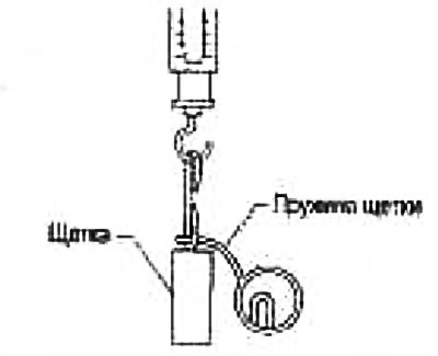
Spring pressure (with a new brush): See section «Technical data and specifications».
If pressure is out of specification, replace.
brush holder
1. Check the insulation between the brush holder (+) and its foundation (-).
If there is continuity, replace.
2. Check if the brush moves freely.
If the brush holder is bent, replace it; if the sliding surface is dirty, clean it.
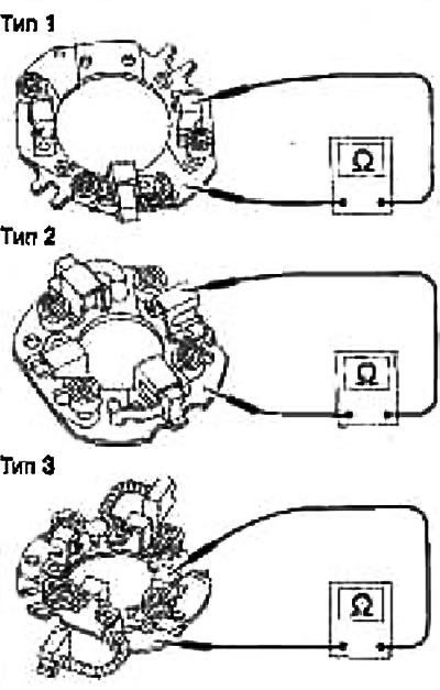
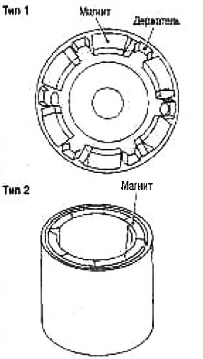
Stator check
The magnet is attached to the stator with glue. Check if the magnet is attached to the stator and if there are any cracks on it. Replace defective components in the kit.
Caution: Do not clamp the stator in a vise or hit it with a hammer.
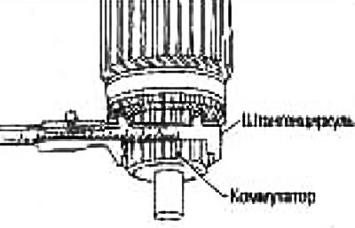
Rotor check
1. Conductivity test (between two adjacent segments).
If there is no continuity, replace.
2. Insulation test (between the commutator blades and the shaft).
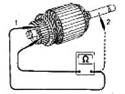
If there is continuity, replace.
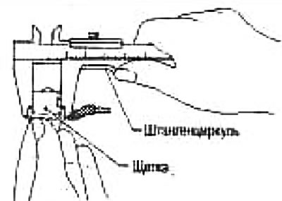
3. Check the surface of the switch.
If the surface is rough, lightly sand it with sandpaper no. 500-600.
4. Check commutator diameter (see fig.).
Minimum commutator diameter: See section «Technical data and specifications».
If diameter is less than specification, replace.
5. Check the depth of the insulating mica from the surface of the switch.
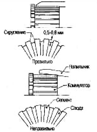
If it is less than 0.2 mm, cut to 0.5-0.8 mm.
Assembly
When reassembling the starter, apply high temperature grease to the bearing, gears and friction surfaces.
Strictly observe the following instructions:
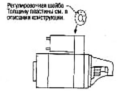
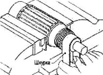
Starter gear protrusion adjustment
Bias
When the starter gear is retracted when the solenoid switch contacts are closed, push it back by hand, eliminate any play, and measure the offset «l» between the leading edge of the gear and the pinion stop.
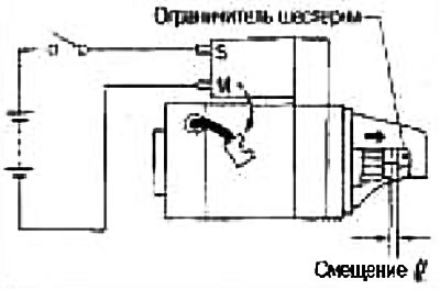
Bias «l»: See section «Technical data and specifications».
If the offset is out of specification, adjust with a shim.