


Note: To perform the work described below, you will need a micrometer and bore gauge.
Removal
1. Turn the crankshaft, bringing the engine to the TDC position of the end of the compression stroke of the first cylinder. In this position, the mark on the crankshaft pulley will be aligned with the pointer on the timing belt cover, and the distributor runner will turn its nose towards the location of the high-voltage wire terminal of the spark plug of the first cylinder.
2. Remove the air cleaner.
3. Release the spark plug wires from the retainers on the cylinder head cover.
4. In a spiral order, moving from the outside in, loosen the cylinder head cover mounting screws on the head. Remove the cover.
5. Loosen the rocker arm axle mounting bolts in several steps and carefully remove the axle assemblies. Place the assemblies in the order they were installed on the engine.
6. To secure the valve tappets in the engine, place rubber bandages on their upper parts, then remove the tappet guides from the cylinder head.
Note: To avoid air entering the hydraulic lifters, do not turn them upside down or tilt them too much.
Disassembly and condition check
1. Partially disassembled rocker arm assemblies, their axles and pushers are shown in the accompanying illustration.
Note: Axles with one mark should be installed in the front pushrod guide, with two marks - in the rear. The layout of the rocker arms on the axles is clear from the illustration.
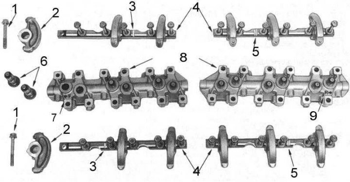
1 - bolt; 2 - rocker arm; 3 - one mark; 4 - rocker arm axles; 5 - two marks 6 - hydraulic tappets; 7 - front mark; 8 - pusher guides; 9 - back mark
2. Loosen the rocker arm axle mounting bolts. Check the axles, remove any burrs or scratches that could damage the rocker arm mounting sockets during the removal process.
3. Remove the rocker arms from their axles, stacking them in the order they are located on the engine.
4. Check the axles for signs of wear and damage. Measure the axle diameters using a micrometer. Compare the measurement results with the standard requirements (see size and adjustment tables at the end of the Manual). Replace excessively worn axles.
5. Check the condition of the landing slots (holes) of the rocker arms. If excessive wear is suspected, measure the internal diameters of the sockets. Compare the results with the size and adjustment tables. Replace the worn rocker arms.
6. Check all tappets for signs of wear, paying particular attention to the surfaces that contact the rocker arms. Excessively worn tappets should be replaced.
Note: If excessive wear of the tappet is detected, the condition of the working protrusion of the corresponding camshaft cam must be carefully checked.
7. Press the top of each hydraulic tappet in turn. If the plunger is pressed deeper than 1.0 mm, the tappet should be replaced. A further check of the tappets can be carried out after assembly by running the engine at 1,000 rpm for 10 minutes. If characteristic noises are detected during this check, remove the components blocking access to the tappets and repeat the first check. Replace all tappets whose plungers are recessed deeper than 1.0 mm.
8. Using a micrometer, inspect the tappet guides for signs of excessive wear. Measure the inside diameters of the bores and the diameters of the corresponding tappets. If the clearance calculated by subtracting the second measurement from the first measurement exceeds the specified clearance, tables of sizes and adjustments (see end of manual), replace the corresponding components.
Assembly and installation
Assembly and installation are carried out in the reverse order of dismantling.
1. Make sure that all channels and openings are clear.
2. Before assembly, lubricate all components with clean engine oil.
3. In the same order, put the rocker arms on the axles from which they were removed. If the installation marks were not applied during dismantling and the rocker arms were mixed up, use the signs illustrated in the accompanying illustration. Please note that the pushrod guides are marked and the rocker arm axles with the same mark must be installed in the front guide.
Note: The rocker arms are asymmetrical in design - see accompanying illustration.
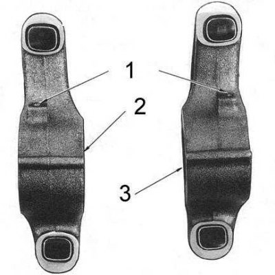
1 - oil holes
2 - cylinders 1, 2 and 3
3 - cylinders 4, 5 and 6
4. Install the hydraulic valve lifters into the guides and secure them there with rubber bands.
5. Install the components into the cylinder head, making sure the rocker arms are correctly positioned in the recesses of the pushrod guides. Tighten the rocker arm axle mounting bolts, but only by hand for now.
Caution! Make sure that the plungers of all pushrods and valve stems are located in the center of the working surfaces of the rocker arms, and that the oil holes of the rocker arms are facing the valve springs.
6. Make sure that the engine is still in the TDC position of the end of the compression stroke of the first cylinder. If necessary, adjust the position of the crankshaft.
7. Tighten the rocker arm axle mounting bolts to the rear pushrod guide to the required torque.
8. Rotate the engine one revolution in the direction of normal rotation until the pointer on the timing chain cover is again aligned with the TDC mark on the crankshaft pulley. Tighten all remaining rocker arm axle and front guide mounting bolts to the required torque.
9. Check the condition and correct position of the cylinder head cover gasket. If there is any doubt, the gasket should be replaced.
10. Install the cover on the cylinder head, screw in the screws and place the seals. Moving in a spiral from the center outward, tighten the screws in several steps to the required force. Connect the engine ventilation hoses.
11. Install the air cleaner. Start the engine and check for leaks.