Note. The following special equipment is required to perform the procedures below: valve spring compression tool, micrometer, plunger-type dial gauge, and flatness gauge (edge of steel ruler).
Removing
Note. The cylinder head can, in principle, be removed as an assembly with the intake manifold and exhaust manifold, however, due to the significant weight and size characteristics of such an assembly, the compilers of this Guide recommend that the following procedure be followed.
1. Disconnect the negative cable from the battery.
2. Take care of protection of a paint and varnish covering of body panels surrounding an impellent compartment.
3. Empty the cooling system.
4. Remove the air cleaner.
5. Remove valve drive assembly, intake manifold and exhaust manifold.
6. Remove the timing belt.
Note. To avoid deformation of a head of cylinders give bolts of its fastening on the hot engine.
7. Give back angular and forward angular bolts of a head of cylinders.
8. In reverse order of tightening, gradually loosen the head mounting bolts.
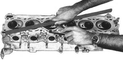
9. With the help of an assistant, remove the cylinder head from the engine, being careful not to damage its mating surface.
Note. Do not turn the engine over after removing the cylinder head. Remember the position of the camshaft guide pin - it should be at the top of its stroke diagram. Installing a head with an incorrectly rotated camshaft will damage the valves and pistons.
Installation
Installation is in the reverse order.
1. Make sure that the mating surfaces of the head and cylinder block are absolutely clean.
2. Check head flatness (see accompanying illustration). If necessary, re-groove it, or replace it.
3. Similarly check up flatness of an interfaced surface of the block of cylinders. If necessary, remove the engine and give the block to the groove.
4. Lay the head gasket on the cylinder block, making sure that all of its holes are correctly placed.
5. Install the head in its place on the cylinder block, lightly lubricate the threads and washers of the bolts and screw in the fasteners.
Note. The head bolt washers must be installed with chamfers to the bolt heads.
6. Loosely screw in the corner bolts.
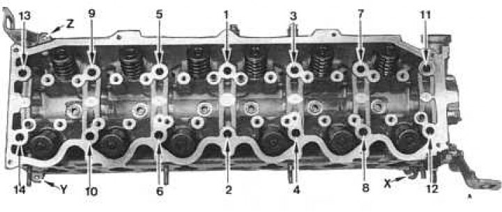
7. Tighten the fasteners in the order shown in the accompanying illustration.
Note. Corner bolts X, Y and Z are tightened after the main fastener has been tightened! Wherein:
- Then tighten them with a force of 78 Nm;
- Completely loosen the bolts in reverse order;
- Re-tighten them to 29 Nm;
- Tighten the bolts with a force of 78÷88 Nm, or (which is preferable) with the help of a goniometer another 100÷105°
8. Tighten the head angle bolts to 9÷12 Nm.
9. Reinstall the valve actuator assembly and the intake piping and exhaust manifold.
10. Put on a timing belt.
11. Prime the cooling system.
12. Start the engine and check for leaks.
Disassembly
Note. Overhaul of the cylinder head requires the use of special equipment. The purchase or rental of such equipment is usually not economically viable when repairing only one head. In view of the foregoing, it would be advisable to entrust the overhaul of the cylinder head to the specialists of the workshop of the dealership of the car manufacturer or service station. In some branded workshops, you can purchase a replacement remanufactured head on an exchange basis, which can significantly reduce vehicle downtime.
1. Remove the cylinder head from the engine.
2. Remove the distributor.
3. Having blocked the gear wheel of the camshaft with a suitable tool, give the bolts of its fastening.
Note. The tool must engage with the front of the wheel, never with its teeth!
4. Remove the gear wheel from the camshaft stub.
5. Give bolts of fastening of a persistent plate of a camshaft, then carefully, trying not to damage bearings in a head, take a shaft from it. The camshaft and its drive components are shown in the accompanying illustration.
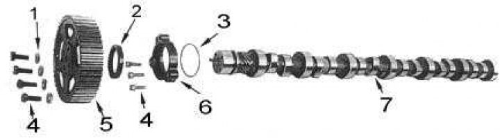
1 - washers; 2 - stuffing box; 3 - sealing ring; 4 - bolts; 5 - gear wheel; 6 - thrust plate; 7 - camshaft
6. Before removing the valves, remove carbon deposits from the walls of the combustion chambers - this will help to avoid damage to the valves and their seats.
7. Lay the head on its side. Using the special tool, compress the valve spring.
8. Remove two crackers of the split lock from the valve spring plate (valve components are shown in the accompanying illustration).
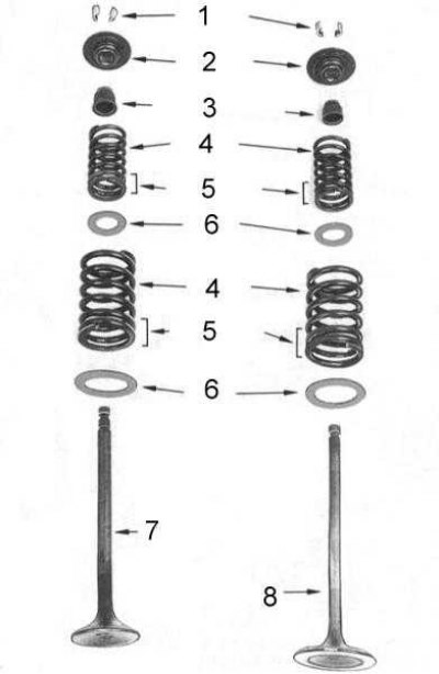
1 - crackers; 2 - plates of springs; 3 - oil seals; 4 - springs; 5 - turns with a shortened pitch; 6 - spring seats; 7 - exhaust valve; 8 - inlet valve
Note. If you have difficulty removing the crackers from the valve spring plate, tap sharply on the edge of the plate with a hammer handle.
9. Release the tool and remove the plate and springs.
10. Use a file to remove all visible small defects in the form of burrs and scuffs from the edges of the groove for installing crackers, then remove the valve from the cylinder head.
11. Acting in the order described, remove the remaining valves with their components. Stack the components in the order in which they are installed on the engine.
Note. For orderly storage of valves, a rail with twelve numbered holes is perfect, into which the valves should be stuck with rods in the order they are installed in the head.
12. Carefully prying, remove the valve stem seals from the valve stems. Throw them away.
Cleaning and checking the condition of the head and its components
1. Thoroughly clean valves, discard defective (with burnouts, cracks and deformation of the rods).
2. Carefully remove accumulated deposits from head inlet and outlet ports, valve stems and valve guides. Be careful not to damage mating surfaces.
3. Clean the mating surface of the head, the water jacket passages, the support and the thermostat housing.
4. Wash the cylinder head in kerosene, rinse with water from a hose, then dry thoroughly to prevent corrosion.
5. Install each valve in the appropriate guide. Raise the valve until the end of its stem is 30 mm above the end of the guide bush. Fix the dial gauge so that its plunger rests against the forming surface of the valve stem shank.
6. Shaking the valve stem in the transverse direction parallel to the plane of the rocker arm, determine the amount of its side play. If the measurement result exceeds 0.2mm, measure the inner diameter of the guide bush and the diameter of the rod, compare the measurement results with the requirements tables of sizes and adjustments, replace excessively worn components. Repeat the test procedure for all remaining valves.
Note. Removal and installation of valve guide bushings require heating the cylinder head to a temperature of 150°÷160°C, in addition, when installing the bushings, they must be properly countersunk, which is why the compilers of this Manual recommend entrusting this work to car service workshop specialists.
7. If there are signs of leakage or deterioration of material due to aging, replace the cylinder head water jacket spherical plugs.
8. Check up flatness of interfaced surfaces of a head and the block of cylinders. Make a groove if necessary.
9. Inspect the camshaft lobes and bearing surfaces for signs of wear and damage.
10. Lay the camshaft with pins in V-shaped blocks and use a dial gauge to evaluate its runout in the area of \u200b\u200bthe central bearing. If the beat exceeds the allowable value (see size and adjustment tables at the end of the manual), replace the shaft.
11. Measure the diameter of the bearing journal and the height of the camshaft lobe lift, compare the results with regulatory requirements (see tables of sizes and adjustments at the end of the guide). If there are signs of excessive wear, replace the shaft.
12. Measure the inside diameter of the camshaft bearing in the cylinder head. Compare the result with the diameter of the bearing journal of the shaft. If the gap exceeds the allowable value (see tables of sizes and adjustments at the end of the guide), replace the head.
13. To measure end play, install the camshaft and its thrust plate into the cylinder head. Attach a dial gauge against the front end of the shaft. Push the shaft all the way forward, then pull it all the way back and read the dial gauge. If the axial play exceeds the allowable value (see tables of sizes and adjustments at the end of the guide), replace the thrust plate.
Restoration of working surfaces of valves and their saddles
Note. This work should be entrusted to a qualified specialist who has the necessary tools. Contact an auto repair shop for help.
1. Turn the plate of each valve at the required angle (see tables of sizes and adjustments at the end of the guide). If necessary, grind the end of the valve stem to the plane (but do not remove more than 0.2 mm of material).
2. Measure the width of the cylindrical part (girdle) valve discs. If it is already the minimum allowable limit (see tables of sizes and adjustments at the end of the guide), valve must be replaced.
3. Check the valve stem for signs of bending. If so, replace the valve.
4. When turning valve seats, use special cutter guides. As a result of processing, a smooth, inextricable working chamfer should be obtained. Excessively worn seats must be replaced.
5. Once the seat has been machined, the seat bevel width must meet the regulations, which are different for inlet and outlet valves (see tables of sizes and adjustments at the end of the guide).
6. To check the development of the contact patch, lubricate the working surface of the valve disc with Prussian blue, then install the valve in the head and rotate, pressing it against the seat. After tearing off the valve disc, a uniform, unbreakable ring should form on the working chamfer of the seat, coaxial to the axis of the seat. Check the finish of all valves/seats in the same way.
Checking the condition of the valve springs
1. Measure the free length of the valve springs. Compare measurement results with regulatory requirements (see tables of sizes and adjustments at the end of the guide).
2. Check the springs for signs of deformation.
3. If a special diagnostic tool is not available, compare the length of the loaded spring with that of the new spring. To do this, rest the springs with their ends against each other, laying a flat plate or washer between them, then compress the assembly in a vice. After closing the vise jaws by approximately 13 mm, the length of a working spring should not differ from the length of a new one by more than 5%. Replace spring if necessary.
Cylinder head assembly
1. Assembly is carried out in the reverse order of dismantling.
2. Before assembling, make sure that the ports and valve seats are absolutely clean - there should not be any traces of foreign materials on their surfaces. Lightly oil the valve guides and install the spring seats.
3. Put the spring seats and new oil caps on the valve guides, make sure the caps fit securely.
Note. Two types of oil seals are used. Caps reinforced with metal inserts are installed on the inlet valves, and for their landing, use a piece of tube or a replaceable head of a suitable diameter. The exhaust valve caps are equipped with a metal ring at the base and can be fitted onto the sleeve with your fingers.
4. When installing the valves, take care not to damage their stems.
5. Install valve springs. Please note that the exhaust valve springs of the first, second and third cylinders are wound in the opposite direction to the others. Also remember that all springs must be installed in shorter pitch coils (usually painted) to the cylinder head.
6. Install the valve spring plate and compress the springs with the special tool.
7. Insert the split lock crackers into the groove on the shaft and release the tool. Lightly tap the end of the rod with a soft-faced hammer to shrink the crackers in the plate. Repeat the procedure for the remaining valves.
8. Reinstall the camshaft. Take care not to damage the bearings by lifting the cams.
9. Install the camshaft thrust plate with a new O-ring. Tighten the fixing bolts to the required torque.
10. Lubricate the new camshaft oil seal with clean engine oil and, using a suitable tool, seat the oil seal against the camshaft with the sponges.
11. Align the hole in the shaft gear with the camshaft guide pin and slide the wheel onto the shaft.
12. Screw in the gear wheel mounting bolts, remembering to place washers under them. The washers should be chamfered on their inner edges towards the bolt heads.
13. Block the camshaft gear with a suitable tool and tighten the mounting bolts to the required torque.
14. Replace the remaining components removed during head removal.