


Table of contents: Removal connecting rod and piston…↓ Checking the condition of the pistons ↓ Checking the condition of the block…↓ Honing of cylinder mirrors ↓ Checking piston clearances ↓ Replacing piston rings ↓ Installation of connecting rod and…↓
Note: The following special equipment is required to perform the following procedures: Cylinder Step Reamer; micrometer and telescopic bore gauge (to check the condition of the cylinders); hon (for restoration of cylinder mirrors) and tools for expanding and compressing piston rings (for mounting and installing connecting rod and piston assemblies).
Removal connecting rod and piston assemblies
Note. In principle, the removal of connecting rod and piston assemblies can be done without removing the engine from the vehicle, although, given the difficulties associated with disconnecting the oil pan and working under the vehicle, this approach does not seem advisable at all. The authors of this Manual recommend performing this work on an engine removed from the vehicle.
Connecting rod and piston assembly components
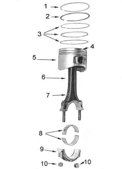
1 - upper compression ring; 2 - lower compression ring; 3 - oil scraper ring sections; 4 - front mark; 5 - piston; 6 - connecting rod; 7 - oil hole; 8 - bearing shells; 9 - lid; 10 - nuts
1. Remove the engine from the vehicle.
2. Place the engine on a mounting stand or sturdy workbench and remove the cylinder head, oil pan and oil pump pickup from the engine.
3. Make sure that the identification marks are present on the connecting rod lower heads and the connecting rod bearing caps of the crankshaft. Try to remember the order of installation of the assemblies.
4. Using a blade-type feeler gauge, check the amount of axial play in the connecting rods. If the play exceeds the permissible value (see size and adjustment tables at the end of the Manual), replace the worn connecting rod.
5. Having brought the piston of the first cylinder to the bottom point of its stroke, loosen the nuts securing the lower connecting rod head cover (connecting rod bearing). Remove the cover.
6. Wipe the bearing shell in the cap and the exposed part of the crankpin with a clean, lint-free cloth, then place a piece of calibrated plastic wire from the Plastigage measuring kit along the journal. Place the cap on the connecting rod and tighten the nuts to the required torque.
7. Unscrew the nuts, remove the cover and, using the scale on the kit packaging, measure the width of the flattened calibrated wire to determine the size of the connecting rod bearing clearance. Compare the measurement result with the standard requirements (see size and adjustment tables at the end of the Manual), if the permissible limit is exceeded, replace the bearing assembly.
8. Repeat the procedure for the remaining connecting rods. Remember the clearance value for each bearing.
9. Remove the lower head caps of all connecting rods one by one, then use a wooden hammer handle to push the assemblies out of the cylinders through the top, then immediately install the caps with inserted liners on the connecting rods. If necessary, before proceeding to extract the connecting rod and piston assemblies, use a special countersink to remove the stepped wear in the upper part of the cylinders.
Note: To protect the crankshaft journals and cylinder bores from damage during the removal of the connecting rod and piston assemblies, place sections of plastic tube on the bearing cap mounting bolts.
10. Remove from pistons (through the top) piston rings and discard them.
Checking the condition of the pistons
1. Inspect the pistons for signs of wear, scratches, scoring and burnout.
2. Remove all traces of carbon deposits from the piston crown and ring grooves.
3. Assess the degree of wear of the piston ring grooves. To do this, take new ones, measure, and check the value of their lateral clearance in the corresponding grooves of each piston. Compare the measurement result with the standard requirements (see size and adjustment tables at the end of the Guide).
4. Inspect the connecting rod bearing shells of all pistons for signs of wear. If wear is detected on the outer edges of the shells, check the corresponding connecting rod for bending.
Note: Since connecting rod straightening requires special equipment, the authors of this Guide recommend that this inspection and repair be performed in a car service workshop.
Checking the condition of the block and cylinder mirrors
1. Check the cylinder mirrors for cracks, scoring, scratches and traces of wear.
2. Using a special bore gauge in a set with a micrometer, measure the diameters of the cylinders in order to assess the degree of their wear and identify ovality and taper. Take measurements in two directions (along and across the block) and at three levels along the height of the cylinders - along the upper limit of the piston stroke, in the middle and at the bottom. The difference between the distances A and B, measured along the upper and lower limits of the piston stroke, determines the ovality of the cylinder, the difference between the measurements A in the upper and lower planes of the working section of the cylinder determines its taper.
3. From the results of six measurements of each cylinder, select the maximum and minimum readings. The difference in these readings can be considered as a criterion for the degree of wear of the cylinder.
4. If the wear of any of the cylinders exceeds the permissible value (see size and adjustment tables at the end of the Manual), all cylinders should be ground to the standard repair size (in excess) with subsequent honing.
Note: The selection of the required repair size from among those provided by the standard is determined by the dimensions of the most heavily worn cylinder.
5. Using a flatness gauge and a blade-type feeler gauge, check the flatness of the upper mating surface of the block (proceed as when checking the flatness of the cylinder head). If the block non-flatness exceeds the permissible value (see size and adjustment tables at the end of the Manual), perform a block drill.
6. Thoroughly wash the block with a suitable solvent and dry it with compressed air, paying particular attention to blowing out oil flows and hard-to-reach cavities.
7. Inspect the block for cracks and other mechanical damage.
Honing of cylinder mirrors
Note: Cylinder faces that are suitable for use with old pistons but require replacement piston rings are subject to honing.
1. To remove polish from cylinder mirrors, use a surface hone with 280 grit sharpening stones.
2. Move the rotating hone nozzle up and down in the cylinder at a speed that allows you to achieve a mesh pattern of notches with an intersection angle of 60°. This treatment ensures optimal conditions for running in the piston rings.
Caution! Do not remove more material from the cylinder mirror than is necessary to remove the polish, otherwise the cylinder diameter and, accordingly, the piston clearance will increase to an unacceptable extent.
3. During processing, lubricate the nozzle and cylinder walls with special honing oil.
Attention! The use of transmission or engine oils, as well as mineral spirits and kerosene for this purpose is not allowed!
4. After honing is complete, thoroughly wipe the cylinder bores to remove all traces of abrasive.
5. After washing and drying the block, wipe the cylinder mirrors again with a clean, lint-free cloth, then lubricate them with engine oil to prevent corrosion.
Checking piston clearances
1. Using a quality bore gauge and micrometer, measure the diameters of all cylinders as described above.
2. Measure the piston diameters at a distance of 47 mm from the piston crown.
3. Subtract the diameter of the corresponding piston from the cylinder diameter to determine the piston clearance. If the calculation results exceed the permissible values (see size and adjustment tables at the end of the Manual), replace the piston or resurface and hone the cylinder at your discretion.
4. After turning the cylinders to the standard repair size and honing, they should be repeated the procedure for determining piston clearances.
Note. If the piston, piston pin or connecting rod require replacement, it should be done in a car service workshop, since to remove/install the pin, the piston must be properly heated to a temperature of 70°C, or a hydraulic press must be used. A special mandrel is required to remove the bushings of the upper connecting rod heads.
Replacing piston rings
1. Select a set of new piston rings that match the size of your vehicle's engine cylinders (respectively standard or repair size).
2. Insert each ring one by one with the bottom of the inverted piston into the least worn part of the cylinder to measure the size of the gaps in their locks. Using a piston to insert the rings into the cylinder allows you to achieve perpendicularity of the ring arrangement.
3. After removing the piston, measure the ring gap using a blade-type feeler gauge.
Note: After measuring the gap in the lock, the ring must be used to complete the piston of this particular cylinder.
4. In accordance with the accompanying illustration, which shows the piston ring sections, place the new rings on the corresponding pistons. Use a piston ring expander. The compression rings should be installed with the stamped marks in the form of letters facing up (to the piston bottom).
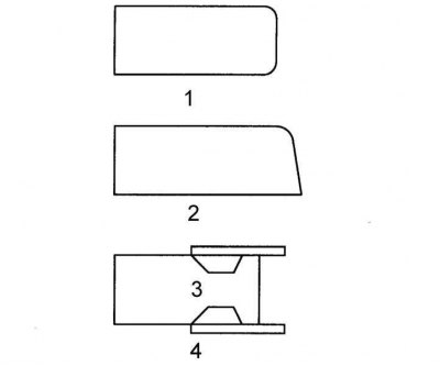
1 - upper compression ring; 2 - lower compression ring; 3 - expander; 4 - oil scraper ring
5. Position the oil scraper ring so that the section and expander locks are not opposite each other.
6. Turn the rings on the piston with the locks as shown in the illustration, where: A = upper compression ring, B = lower compression ring, C = oil scraper ring expander, D = upper section of oil scraper ring, E = lower section of oil scraper ring.
Installation of connecting rod and piston assemblies
1. Lubricate the piston assembly and the walls of the first cylinder with clean engine oil.
2. Turn the crankshaft and bring the first connecting rod journal of the crankshaft to the BDC position. Wipe the journal dry with a clean rag, then lubricate it with clean engine oil.
3. Remove the connecting rod cap and wipe the bearing shells, or replace them if necessary. Lubricate the shells with clean engine oil.
4. Place pieces of plastic tube on the cover mounting bolts to protect the cylinder walls and shaft journal.
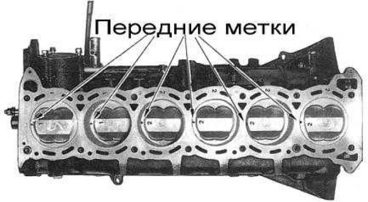
5. Compress the piston rings with a special tool, then insert the connecting rod assembly into the first cylinder by tapping the piston crown with a hammer handle and simultaneously guiding the connecting rod head onto the connecting rod bearing journal of the crankshaft.
Note. The piston must be inserted into the cylinder with a front label on the bottom (see the accompanying illustration - numbers on the cylinders and characterize the dimensional parameters (standard or repair)) forward along the engine, the piston ring compression tool mandrel must be pressed tightly against the block along the entire perimeter during the entire time the connecting rod assembly is installed.
6. Remove the protective plastic tubes from the connecting rod lower head cover mounting bolts.
7. Place the bearing cap on the connecting rod head, making sure that the mounting marks made during dismantling are aligned. Tighten the fasteners:
- At the first stage, tighten the nuts with a force of 14÷16 Nm;
- Then tighten the nuts with a force of 38÷44 Nm, or (which is preferable) according to the protractor another (60°÷65°).
8. Proceeding in a similar manner, install the connecting rod and piston assemblies into the remaining (corresponding to them) cylinders.
(See the source on the portal: www.NISSANBOOK.ru)
9. Further installation is carried out in the reverse order of dismantling.