Note. You will need a puller to perform the procedures below (to remove the crankshaft gear), micrometer and plunger-type dial gauge.
Removing
1. With the engine removed from the vehicle, remove the timing belt, oil pan, oil pump intake, oil pump, flywheel and rear oil seal holder.
2. Remove the spark plugs from the engine.
3. Give fixing nuts and remove covers of the lower heads of connecting rods, folding them in the order of installation on the engine. Carefully push the connecting rod and piston assemblies up in the cylinders, not reaching the upper limit of the piston stroke.
Note. Check for identification marks on the connecting rods and connecting rod bearing caps.
4. Using a blade type probe (on the fourth main bearing - see accompanying illustration), or a dial gauge, check the axial play of the crankshaft (fix the meter on the front wall of the block with a plunger to the end of the shaft).
5. If using a dial gauge, push the crankshaft all the way back and reset the gauge.
6. Push the shaft all the way forward and read the dial gauge. If the running surfaces of the thrust center main bearing are in good condition, the measurement result should not exceed 0.30 mm.
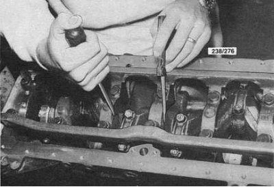
7. In several stages, loosen the bolts of the common main bearing cap - proceed in the reverse order of their tightening. The components of the common main bearing cap are shown in the accompanying illustration. Note the location of the long bolts.
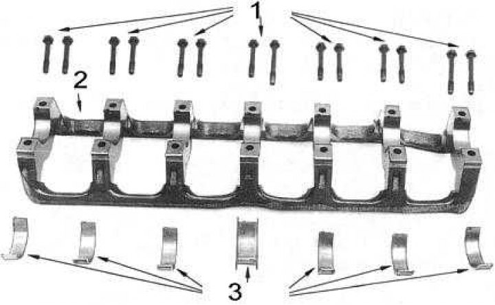
1 - bolts
2 - cover
3 - bearing shells
8. Before removing the crankshaft, you can measure the clearances in its main bearings using a calibrated plastic wire from the Plastigage kit:
- Wipe the bearing surfaces thoroughly with a clean, lint-free cloth;
- Lay seven lengths of calibrated wire from the measuring set along the necks of the shaft (slightly off axis);
- Install the common main bearing cap and diagonally, moving from the center outward, tighten the bolts of its fastening;
Note. Do not allow the shaft to rotate after laying pieces of wire on it.
- Give the bolts and carefully remove the cover, remove the lower bearing shells;
- By measuring the width of the flattened pieces of calibrated wire on the scale on the packaging of the measuring set, determine the gaps in the main bearings of the shaft;
- Where the wire is flattened, the gap is smaller, and vice versa.
9. Carefully remove the crankshaft from the crankcase - try not to damage or drop the upper main bearing shells, especially if you do not plan to replace them.
10. If the liners are to be replaced, remove them from their beds in the crankcase.
Status check
1. Evaluate the condition and degree of wear of the crankshaft main and connecting rod journals, check them for taper and ovality. If necessary, turn the necks to the nearest standard repair size.
Note. Even if only one of the journals is worn or damaged (main or connecting rod) all the rest should also be pierced (respectively main or connecting rod). At the same time, new bearing shells of the appropriate repair size should be prepared.
2. If the nature of wear does not allow to restore the neck of the shaft by turning, the shaft should be replaced.
3. Check the condition of the thrust surfaces of the central bearing (see accompanying illustration). In case of detection of deep cavities and workings, replace the bearing shells, which should normalize the axial play of the crankshaft.
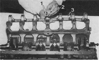
1 - built-in thrust plates
2 - thrust bearing shell
3 — a cover of radical bearings
4. Even if the clearances in the main bearings are found to be satisfactory, check the liners for scratches, burrs, cracks, cavities and other defects. Replace defective earbuds if necessary (in pairs).
5. Lay the crankshaft ends in V-shaped blocks and use a dial gauge to measure the amount of its runout in the area of the central main bearing. If the result exceeds 0.10 mm, the shaft must be replaced.
Installation
Installation is in the reverse order.
1. Check the patency of all oil flows and the cleanliness of all shaft journals.
2. Once again wipe loose leaves of all bearings and grease them with pure motive oil. Position your liners correctly in your beds.
Note. When installing the upper main bearing shells, make sure that the oil holes in them are aligned with the corresponding holes in the beds. The top liners are distinguished by the presence of oil grooves.
3. Lay the crankshaft in the cylinder block, tucking the connecting rod journals into the lower heads of your connecting rods.
4. Lay the lower main bearing shells in their beds in the cover. Make sure that the landing tabs of the liners fit into the reciprocal grooves in the cover.
5. Lubricate the lower main bearing shells with clean engine oil and install the main bearing cap assembly to the engine.
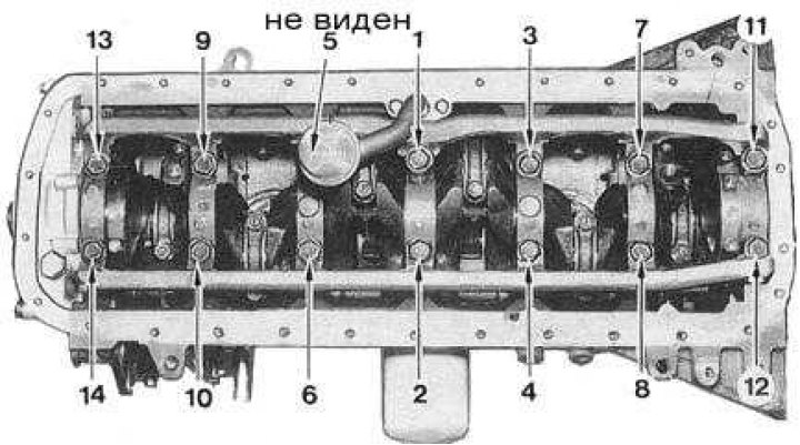
6. Screw in the cover fastening bolts and tighten them in several stages with a force of 46÷52 Nm in the order shown in the accompanying illustration.
Note. Make sure the long bolts are screwed into their original holes.
7. Check up freedom of rotation of a cranked shaft. Measure the axial play of the shaft.
8. Replace the crankshaft rear oil seal and install the holder on the block.
9. Place the bottom ends of the connecting rods on your shaft journals. Lubricate the connecting rod bearing shells with clean engine oil and install the bearing caps on the lower heads of your connecting rods. Track conformity of identification marks of rods and their covers. Tighten the connecting rod bearing caps to the correct torque.
10. Install all components removed during disassembly.