Removal and disassembly
1. Remove the timing belt.
2. Remove the gear and rear guide plate from the crankshaft.
Note. To prevent damage to the oil pump/crankshaft seal when removing the pump, remove the key from the crankshaft drive pinion.
3. Give bolts of fastening of the oil pump to the block of cylinders. Tapping on the bottom of the inner surface of the pump, remove it from the crankshaft trunnion. Throw away the pad.
Note. The internal gear of the oil pump is driven by two flats machined into the crankshaft.
4. Give fixing screws and remove the back cover of the oil pump (oil pump components are shown in the accompanying illustration).
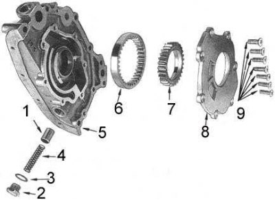
1 - plunger; 2 - cork; 3 - gasket; 4 - spring; 5 - body; 6 - outer gear; 7 - internal gear; 8 - back cover; 9 - screws
5. Carefully, remembering their installation positions, remove the inner and outer gears of the oil pump from the pump housing.
6. Turn out a stopper of the reducing valve, take a saddle of a spring, a spring and a plunger.
7. Carefully remove the crankshaft oil seal from the oil pump - use a special puller or a flat-bladed screwdriver. Discard the seal.
Status check
1. Thoroughly wash all oil pump components in a suitable solvent, then dry them.
2. Inspect the pump housing and cover for signs of wear, deformation, or other damage.
3. Inspect the relief valve plunger for defects.
4. Check pressure reducing valve spring for damage, compare its performance (length and compressive strength) with the parameters of the new spring.
5. Using a blade-type feeler gauge, measure the gap between the teeth of the inner and outer gears and the crescent spacer. If the clearance is out of range (see tables of sizes and adjustments at the end of the guide), replace both gears.
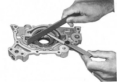
6. Using a feeler gauge and flatness gauge (edge of steel ruler) check the clearances between the end surfaces of both gears and the pump cover (see accompanying illustration). When the measurement results are out of range (see tables of sizes and adjustments at the end of the guide) replace both gears and/or pump housing.
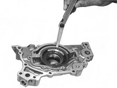
7. Measure the clearance between the outer gear and the wall of the pump housing (see accompanying illustration). Replace outer gear and/or housing if necessary.
8. Check the condition of the oil intake strainer. If blockage or damage is found, clean or replace screen.
Assembly and installation
Assembly and installation of the pump are carried out in the reverse order of its dismantling.
1. Check the cleanliness of the gland seat, lightly lubricate the new gland around the perimeter with sealant. Fit the stuffing box into the seat flush with the end of the pump housing (components are shown in the accompanying illustration).
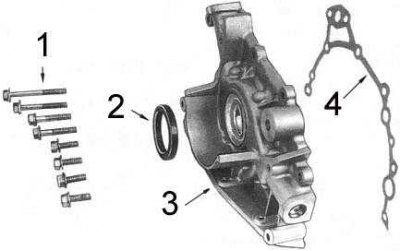
1 - bolts; 2 - stuffing box; 3 - oil pump; 4 - gasket
2. Install the pressure reducing valve components into the pump assembly, tighten the plug with a force of 39÷69 Nm.
3. Install the outer gear into the pump housing (larger chamfer on the outer edge to the rear cover of the pump).
4. Install the inner gear (grooved side towards the back of the pump).
5. Lubricate the gears with engine oil and install the rear pump cover. Tighten the fixing screws with a force of 4÷5 Nm.
6. Coat both sides of the new pump gasket with sealant.
7. Lightly oil the seal lips and slide the pump assembly onto the crankshaft trunnion, making sure the inner gear flats engage the crankshaft properly.
8. Align position of assembly of the pump and its laying on the block of cylinders and screw fixing bolts. Tighten the bolts with a force of 9÷11.8 Nm.
9. Install the oil pan and oil pickup assembly on the engine, fill the engine with the required amount of oil of the required grade.
10. Install the crankshaft gear, timing belt and vibration damper.
11. Start the engine, warm it up to normal operating temperature. Check for oil leaks and make any necessary corrections.