Attention.
- Do not bake blows on the steering column when removing it.
- Mark the intermediate shaft and steering column assembly before removing the intermediate steering shaft.
- Do not turn the steering wheel when the vehicle is stationary because the electric motor and the electric power steering control unit are too hot.
- The steering column assembly has a significant mass. Be careful when removing the steering column assembly from the vehicle.
- Do not place the steering column assembly near objects with a strong magnetic field.
- The steering column assembly cannot be disassembled.
Removing
1. Set the front wheels of the vehicle to the straight ahead position.
2. Set the steering wheel to the highest possible position.
3. Remove the steering wheel.
4. Remove the steering column cover.
5. Remove contact disc.
6. To remove the block of understeering switches.
7. To remove the bottom facing of the panel of devices.
8. Remove the instrument cluster.
9. Disconnect all switch connectors installed on the steering column, and then disconnect the wires from the steering column assembly.
10. Remove the intermediate shaft of the steering column as follows:
Loosen the mounting bolt (1).
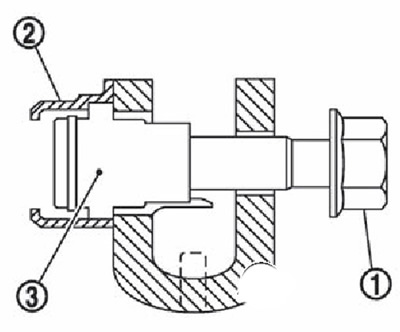
Remove the pressed-on cam nut retainer (2) from the intermediate shaft yoke.
Remove cam nut (3).
11. Remove the steering column assembly.
Check after removal
Check all elements of the steering column assembly for damage or other defects. Replace the steering column with a new one if any abnormalities are found.
Measure the moment of resistance to rotation of the steering column assembly using a special dynamometer (ST3127S000). Replace the steering column assembly with a new one if the value obtained exceeds 2.5 Nm.
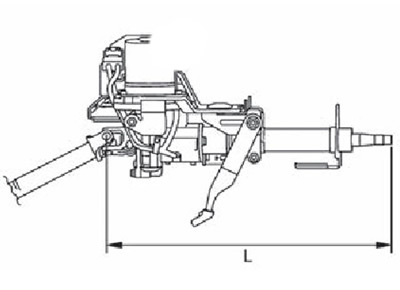
Measure length «L» the steering column shown in the figure if the vehicle has been subjected to even a minor collision. Replace steering column assembly (with electric motor, gearbox, position sensor) if the length is not correct (495 mm).
Installation
Installation is done in the reverse order of removal, with the following features noted.
Attention.
- Do not strike the steering column when removing it.
- Place match marks on the intermediate shaft and steering column assembly before disconnecting the intermediate shaft.
- Avoid taxiing while the vehicle is stationary (the motor and the electric booster control unit are overheating).
- The steering column assembly has a significant mass. Be careful when removing the steering column assembly from the vehicle.
- Do not place the steering column assembly near objects with a strong magnetic field.
- The steering column assembly cannot be disassembled.
- Do not reuse the cam nut and fixing bolt.
Note.
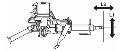
- Steering column height adjustment range (L1): 40 mm.
- Steering column reach adjustment range (L2):±25 mm.
1. Make sure that all parts of the cam nut retainer are removed.
2. Install the link on the intermediate shaft, making sure that there is no gap between the link and the intermediate shaft.
3. Fully insert the cam nut.
4. While holding the cam nut in place by hand, insert the bolt and tighten to the specified torque. Ensure that the cam nut is in the correct position during tightening (along the axis).
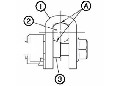
5. After connecting the intermediate shaft, make sure there is no gap (A) between earring (1), intermediate shaft (2) and cam nut (3).
Attention. Adjust the neutral position of the steering angle sensor.
Check after installation
Check all elements of the steering column assembly for damage or other defects. Replace the steering column with a new one if any abnormalities are found.
Check the play and neutral position of the steering wheel, as well as the effort on the steering wheel and the angle of rotation of the steered wheels.
Check steering column height adjustment ranges «L1» and departure «L2».
Note.
- Steering column height adjustment range (L1): 40 mm.
- Steering column reach adjustment range (L2):±25 mm.