


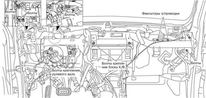
Fastening of the K/V block
Assembly of the K/V block of models with manual control

1*,5,11,13,23 - Screw; 2* - Aspirator line; 3/15 - Right/Left Fan Shroud; 4/14 - Right/left casing; 6/10 - Right/left air duct "to the feet"; 7 - Cooling hose; 8 - Heater fan electric motor; 9 - Air mixing flap; 12 - Fixators; 16 - Aspirator; 17 - Ventilation flap; 18 - Glass blower rod; 19 - Glass blower flap; 20 - Air supply valve to the feet; 21 - Heater radiator; 22 - Radiator pipe cap; 24 - Evaporator temperature sensor; 25 - Radiator tube gasket; 26 - Lower fan shroud; 27,29*,31,33,35* - Screw; 28 - Bracket; 30 - Electric motor* (thrust**) of air supply flap; 32 - Resistor assembly; 34 - Connecting casing; 36* - Electric damper motor 9; 37 - Valve stem 9; 38 - Throttle lever 9; 39 - Spring; 40,42,57,60*,65 - Screw; 41 - Heater tube retainer; 43 - Bolts; 44 - Expansion valve; 45 - Isolator; 46 - Cabin filter; 47 - Throttle rod* (lever**) 49; 48/50 - Left/right damper housing 49; 49 - Air supply flap; 51 - Evaporator; 52 - Expansion valve cover; 53 - Ventilation/blowing lever; 54 - Ventilation/blowing rod; 55 - Ventilation/blowing draft; 56,58,66 - Washer; 59 - Throttle valve stem; 61 - E/motor of the mode flap; 62 - Throttle lever 20; 63 - Damper rod 20; 64 - Main damper
1. Discharge the air conditioning system in a specialized workshop.
Read more on the website (NISSANBOOK.RU)
2. Drain the engine cooling system (see section Replacing the coolant).
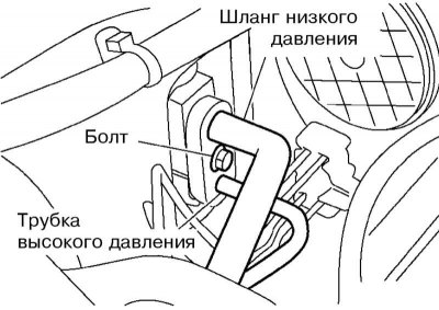
3. Disconnect the low pressure flexible hose and high pressure pipe from the evaporator. Plug the open holes.
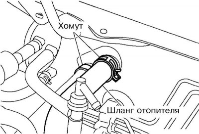
4. Disconnect the hoses from the heater radiator and plug the open holes.
Note: Coolant may leak when the hoses are disconnected.
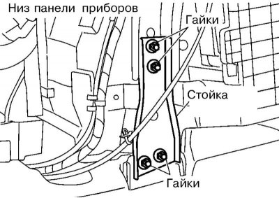
5. Remove the instrument panel (see Chapter Body), electrical wiring clamps and instrument panel stand.
6. Remove the screws and release the air duct clamps.
7. Remove the A/C unit mounting bolts, steering gear bolts and steering column bolts. Release the wiring harness clamps (see illustration Fastening of the K/V block).
8. Remove the on-board control module (BCM) – see Chapter On-board electrical equipment.
9. Remove the steering gear and then the crankcase unit.
10. The components of the K/V unit assembly are shown in the illustration Assembly of the K/V unit of models with manual control.
11. Installation is carried out in the reverse order. Replace all O-rings on the pipes. When installing the A/C unit, make sure that its drain hole matches the drain pipe. Tighten the fasteners with the required force. Finally, fill the cooling and A/C systems and make sure there are no leaks.