Information about diagnostic tools
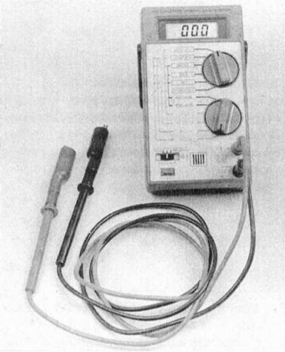
1. Checking the correct functioning of the components of the injection systems and reducing the toxicity of exhaust gases is carried out using a universal digital meter (multimeter) (see accompanying illustration). The use of a digital meter is preferred for several reasons. Firstly, it is quite difficult for analog devices to (sometimes impossible), determine the result of the indication with an accuracy of hundredths and thousandths, while when examining circuits that include electronic components, such accuracy is of particular importance. The second, no less important, reason is the fact that the internal circuit of a digital multimeter has a fairly high impedance (the internal resistance of the device is 10 mΩ). Since the voltmeter is connected in parallel to the circuit under test, the measurement accuracy is the higher, the less parasitic current will pass through the device itself. This factor is not significant when measuring relatively high voltage values (9÷12 V), however, it becomes decisive in the diagnosis of elements that produce low-voltage signals, such as, for example, an oxygen sensor, where it is a matter of measuring fractions of a volt.
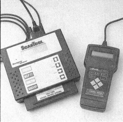
2. The most convenient devices for diagnosing car engine control systems are scanner-type hand-held readers (see accompanying illustration). First generation scanners are used to read fault codes for OBD-I systems. Before use, the reader should be checked for compliance with the model and year of manufacture of the vehicle being checked. Some scanners are multifunctional, due to the possibility of changing the cartridge depending on the model of the car being diagnosed (Ford, GM, Chrysler, etc.), others are tied to the requirements of regional authorities and are intended for use in certain areas of the world (Europe, Asia, USA, etc.). Recently, reading devices such as hand-held scanners such as Actron Scantool or AutoXray XP240 have become absolutely indispensable in the diagnosis of engine control systems of modern cars
General description of the OBD system
- All models described in this manual are equipped with an on-board diagnostic system (OBD).
- The main element of the system is the onboard processor, more often called the electronic module for controlling the operation of the power unit (RSM). The PCM is the brain of the engine management system. The initial data is fed to the module from various information sensors and other electronic components (switches, relays, etc.). Based on the analysis of the data coming from the information sensors and in accordance with the basic parameters stored in the processor memory, the PCM generates commands for the operation of various control relays and actuators, thereby adjusting the operating parameters of the engine and ensuring maximum efficiency of its output with minimum fuel consumption.
- Engine management/emission control system components are subject to a special extended warranty. You should not attempt to independently diagnose PCM failures or replace system components until the expiration of this obligation - contact Nissan authorized service stations.
Information sensors
- Camshaft position sensor (SMR) - The sensor generates information signals, based on the analysis of which the PCM determines the current valve timing and engine speed, using the information received when controlling the injection sequence and ignition of the air-fuel mixture in the combustion chambers.
- Sensor (And) crankshaft position (TFR) - Latest models use two TFR sensors, while earlier models used only one such sensor. The signals coming from the sensors are used by the PCM as a reference when determining the engine speed and the TDC positions of the piston of each of the cylinders. Based on the information received, the PCM controls the sequence of injection and ignition of the air-fuel mixture in the combustion chambers. In OBD-II systems, the signals generated by the TFR sensors are also used in the diagnosis of failures of the power unit.
- Engine coolant temperature sensor (EATING) - Based on the information coming from the sensor, the PCM makes the necessary adjustments to the composition of the air-fuel mixture and the ignition timing, and also controls the operation of the EGR system.
- EGR temperature sensor - The information coming from the sensor is used to determine the intensity of exhaust gas recirculation into the intake tract of the engine.
- Fuel temperature sensor - The PCM uses the information provided by the sensor when diagnosing system component failures.
- intake air temperature sensor (IAT) - The PCM uses information from the IAT sensor to make adjustments to injection parameters, ignition timing settings, and to control the operation of the EGR system.
- Knock sensor - The sensor is a piezoelectric element that reacts to changes in the intensity of engine vibrations. Based on the analysis of the information coming from the sensor, the PCM performs adjustments to the ignition timing in order to timely eliminate the detonation of the air-fuel mixture that occurs in the combustion chambers, which is fraught with premature wear of the internal components of the engine.
- Absolute pressure sensor in the pipeline (IDA) (later models) - The sensor monitors variations in the depth of vacuum in the intake manifold associated with changes in crankshaft speed and engine load, and converts the information received into an amplitude signal. The information from the sensor is used by the control module in diagnosing engine failures.
- Air mass meter (MAF) - The MAF sensor determines the volume and weight parameters of the air flow entering the intake pipeline. A filament is used as a sensitive element in the sensor. The PCM uses the information provided by the MAP and IAT sensors to make fine adjustments to the injection parameters.
- Oxygen sensor (Lambda probe) - The sensor generates a signal whose amplitude depends on the ratio of the amount of oxygen (O2), contained in the exhaust gases of the engine and the outside air. Based on the information coming from the sensor, the PCM determines the parameters of the air-fuel mixture, promptly enriching or depleting it.
- Power steering fluid pressure switch (PSP) - Based on the information coming from the PSP sensor-switch, the PCM provides an increase in idle speed (by actuating the IAC valve) in order to compensate for the increasing loads on the engine associated with the operation of the power steering during maneuvers.
- Throttle position sensor (TPS) - The sensor is located on the throttle body and connected to the throttle shaft. Based on the amplitude of the TPS signal output, the PCM determines the throttle opening angle (controlled by the driver from the gas pedal) and adjusts the fuel supply to the inlet ports of the combustion chambers accordingly. The failure of the sensor, or the weakening of its fastening, leads to interruptions in injection and violations of the stability of the idle speed.
- Vehicle speed sensor (VSS) - As its name implies, the sensor informs the processor about the current vehicle speed.
- Other parameters controlled by PCM - In addition to the sensors listed above, the PCM also receives additional information about the functioning of various components and systems that determine the performance of the engine. Other systems and components managed by PCM include the following:
- Air conditioning system;
- ABS;
- Accumulator battery (output voltage);
- EVAP system;
- Ignition switch;
- Launch enable switch;
- Ground circuits;
- Transmission operation control system.
Executive devices
- The relay of management of functioning of the clutch K/V - PCM cuts off the A/C compressor during hard acceleration.
- Pilot lamp "Check engine" - The PCM turns on this warning lamp when there is a malfunction in the engine management system.
- Relay for controlling the functioning of the fans of the cooling system - The PCM controls the operation of the cooling fans based on the analysis of signals from the coolant temperature sensor.
- EGR Vacuum Control Solenoid Valves - The PCM controls the opening degree of the EGR vacuum valve through a special intermediate solenoid valve.
- EGR valve - On late models, the PCM controls EGR flow through the electronic EGR valve.
- Canister purge valve - This solenoid valve, when actuated by the PCM, purges the EVAP system's charcoal canister, expelling accumulated fuel vapors inside it into the engine intake tract.
- Fast idle control solenoid valve - This valve is used on the latest models and serves to increase idle speed in cold weather. In fact, this valve acts as an air damper on carburetor models.
- Front suspension support of the power unit - On some models, the PCM also controls the stiffness of the front engine mount depending on the vehicle speed. Vibration is minimized by selecting one of two support settings.
- Fuel Injectors - PCM ensures that each of the injectors is switched on individually in accordance with the established firing order. In addition, the module controls the duration of the opening of the injectors, determined by the width of the control pulse, measured in milliseconds, which determines the amount of fuel injected into the cylinder. More detailed information on the principle of operation of the injection system, replacement and maintenance of injectors is given in Chapter 7.
- Fuel pump relay - The relay is activated by the control module when the ignition key is turned to the START/RUN position. When the ignition is turned on, the relay energizes the fuel pump, which provides a pressure increase in the path of the car's power system. For more information on the location and function of the relay, see Chapters 5 and 31.
- Idle speed control valve (IAC) - The IAC valve controls the amount of air bypassing the throttle when the throttle is closed or in the idle position. The opening of the valve and the formation of the resulting air flow is controlled by the PCM.
- Oxygen sensor heater - The operation of this device is controlled by PCM. The heater quickly heats up the l-probe to normal operating temperature.
- Power transistor - The transistor amplifies the ignition signal generated by the PCM and at the right time produces an instantaneous ground to the mass of the primary circuit of the ignition system, which causes the generation of an explosive signal generated by the coil in the secondary circuit of the system (ami) directly to the spark plugs.
- Power valve control solenoid - On later models, the operation of the power valve is controlled by the PCM through a special solenoid.
- Transmission Function Control Module (TCM) - The TCM, being a control module separate from the PCM, receives signals from various information sensors, such as VSS, start enable switch, turbine shaft speed sensor, TPS, CMP, etc., and uses the received data when determining the moment of gear shifting AT, the required pressure in the path and the moment of blocking the rotation converter.
Reading trouble codes
If a malfunction is detected that repeats in a row during the spirit of trips, the PCM issues a command to turn on the warning lamp built into the instrument panel "Check engine", also called the failure indicator. The lamp will remain lit until the disturbance disappears and does not reappear for three or more trips.
Control unit with one LED
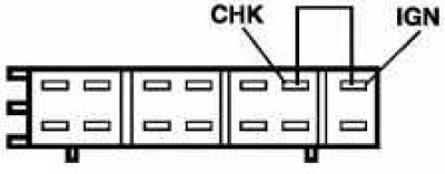
Turn on the ignition. Jumper pins IGN and CHK connector and after 2 seconds. remove the jumper. Count the flashes of the lamp. The number of long flashes corresponds to the number of tens of code, the number of short flashes corresponds to the number of units. If it is necessary to clear the memory, bridge the above contacts again and after 2 seconds. remove the jumper. Switch off the ignition.
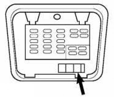 |  |
Location of the diagnostic connector. To read the codes, jumper the indicated contacts
Control unit with red and green LEDs
 |  |
For reading fault codes by means of diagnostic lamps, or a control lamp "Check engine" use the selector located on the side of the PCM
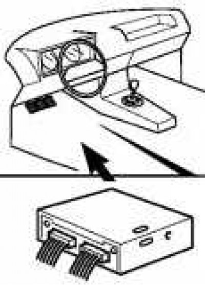
To read fault codes, it is necessary to provide access to the PCM in order to switch the selector to display codes using diagnostic lamps / warning lamp "Check engine". The PCM must be removed from its support bracket (without disconnecting the wiring) and follow the instructions below.
- Turn on the ignition (without starting the engine). Pilot lamp "Check engine" on the instrument panel should remain on, which confirms that power is being supplied to it from the PCM and that the lamp itself is working.
Attention! Violation of the procedure described below may lead to accidental clearing of PCM memory!
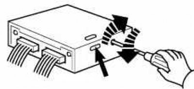
- Using a screwdriver, turn the selector on the PCM wall clockwise as far as it will go. Both LEDs should start flashing simultaneously, - after three flashes turn the selector counterclockwise as far as it will go;
- Carefully observe the functioning of the diagnostic lamps. The red LED is used to display dozens of fault codes, the code units are illuminated by a green diode. For example, code 43 (TPS chain) will look like this: four flashes of a red diode, then three flashes of green. The absence of violations detected by the system is indicated by the display of code 55 (see below fault code map);
- When the ignition is turned on again, after turning it off in the process of reading the codes, the system automatically cancels the results of the previous search and the reading procedure must be restarted.
Note. Starting the engine automatically blocks access to the self-diagnosis system.
If turning the selector fully counterclockwise in step b) produce at the moment after:
- 1st glimpse the lambda probe test mode will turn on (Both diodes are on). Start the engine. The system will perform a self-diagnosis and if there are no faults, the green LED will flash. The green LED is constantly on - the mixture is too lean. The green LED is off - the mixture is too rich. The red LED lights up at the end of the self-diagnosis.
- 2nd glimpse the test mode of the mixture quality control loop will turn on (green diode is on, red is off). Start the engine. The system will perform a self-diagnosis and if there are no faults, the green LED will flash. The red LED is constantly on - the mixture is too lean. The red LED is off - the mixture is too rich. The red LED flashes together with the green - the mixture is optimal.
- 4th glimpse Throttle Position/Vehicle Speed Sensor Loop Check Mode will be activated (red diode on). Start the engine. The red LED should flash on and off each time you press the gas pedal. When the car is moving, the green diode should light up when the speed exceeds 19 km/h.
- 5th glimpse the dynamic check mode will be activated. Start the engine and, changing the speed, observe the diodes.
- One flash of red - a malfunction in the crankshaft position sensor circuit;
- Two flashes of green - a malfunction in the air flow meter circuit;
- Three flashes of red - a malfunction in the fuel pump circuit;
- Four flashes of green - a malfunction in the ignition system circuit.
Stop the engine.
Clearing ECM/PCM Memory
After the violations identified during the diagnostic process are eliminated, the PCM memory should be cleared of the fault codes recorded in it.
Attention! Clearing the memory by disconnecting the wire from the battery also erases the basic parameters and disrupts the stability of the idle speed for the first time after starting the engine.
- Read the codes of malfunctions written down in memory of system;
- Wait at least two seconds, then turn the selector on the PCM wall all the way clockwise - the LEDs should start flashing;
- After four flashes of the diodes, turn the selector counterclockwise as far as it will go;
- Switch off the ignition.
List of fault codes of the self-diagnosis system
| Code number | Possible reason for rejection |
| 11 | Malfunction in a chain of the gauge of turns of the engine/sensor of position of a cranked shaft |
| 12 | Malfunction in a chain of a measuring instrument of an air stream VAF/mass of air MAF |
| 13 | Malfunction in a chain of the gauge of temperature of a cooling liquid EST |
| 14 | Malfunction in a chain of the gauge of speed of the car VSS |
| 21 | Malfunction in a chain of a signal of ignition |
| 22 | Malfunction in a chain of the fuel pump |
| 23 | Malfunction in a chain d/switch of the closed position throttle gate |
| 24 | Malfunction in a chain d / the switch of completely open position of a throttle shutter / position "P" "N" AT |
| 25 | Malfunction in a chain of the valve of additional air of IAC |
| 26 | Malfunction in a chain of the sensor of pressure of a turbocharger |
| 28 | Overheat |
| 31 | Air Conditioner/No Faults (models without air conditioning) / Violation of the proper functioning of the PCM (engines GA16i, CA18DE) |
| 32 | Malfunction in a chain of a signal of a starter |
| 33 | Malfunction in a chain of the oxygen gauge |
| 34 | Malfunction in a chain of the gauge of a detonation/sensor of provision of a throttle valve (SR20Di engine) |
| 35 | Malfunction in a chain of the temperature sensor EGR |
| 41 | Malfunction in the IAT intake air temperature sensor circuit |
| 42 | Malfunction in a chain of the sensor of temperature of fuel |
| 43 | Malfunction in the TPS throttle position sensor circuit |
| 44 | No faults |
| 45 | Leaks in injection injectors |
| 51 | Malfunction in a chain of a signal of injection of fuel |
| 54 | Malfunction in a chain of a signal of an automatic transmission АТ |
| 55 | No trouble codes in system memory |
Diagnostics of security systems
Produced by the SRS warning lamp on the dashboard or using a diagnostic lamp.
Models with pyrotechnic belt tensioner
With a diagnostic lamp
With the ignition off, bridge pins 7 and 11 of the diagnostic connector through a lamp of no more than 3.3W. Turn on the ignition. If everything is in order, the lamp will go out after about 6 seconds. If the lamp flashes, the wiring of the pyrotechnic belt tensioner device or the control unit may be damaged.
By SRS warning light
With the ignition off, open the driver's door and turn the ignition on. Make sure the lamp is on and press the driver's door switch 5 times within 7 seconds. 2 seconds after the lamp goes out, it will start issuing flashing codes.
| Code number | Possible reason for rejection |
| 11 | Damage to front impact sensor wiring. SRS control unit |
| 12 | Damage to driver airbag wiring. SRS control unit |
| 13 | Damage to front impact sensor wiring. SRS control unit |
| 17 | Damage to the wiring of the SRS control unit |
| 18 | Damage to passenger airbag wiring. SRS control unit |
| 19 | Multiple defects in wiring, control unit, shock sensor, airbag |
Diagnosis of the anti-lock brake system
Start the engine and drive the car at a speed of 30 km/h for at least 1 minute. Switch off the ignition and short the output 4 of the diagnostic connector to the housing. Turn on the ignition and read the codes on the flashes of the ABS warning lamp. Do not press the brake pedal during testing.
| Code number | Possible reason for rejection |
| 12 | Start issuing codes. |
| 18 | Wheel speed sensor rotor. |
| 21 | An open in the right front wheel speed sensor circuit. |
| 22 | Short circuit in the right front wheel speed sensor circuit. |
| 25 | An open in the left front wheel speed sensor circuit. |
| 26 | Short circuit in the left front wheel speed sensor circuit. |
| 31 | An open in the right rear wheel speed sensor circuit. |
| 32 | Short circuit in the right rear wheel speed sensor circuit. |
| 35 | An open in the left rear wheel speed sensor circuit. |
| 36 | Short circuit in the left rear wheel speed sensor circuit. |
| 41 | Output e / magnetic valve of the right front wheel. |
| 42 | Entrance e/magnetic valve of the right forward wheel. |
| 45 | Output e / magnetic valve of the left front wheel. |
| 46 | Entrance e/magnetic valve of the left forward wheel. |
| 51 | Output e / magnetic valve of the right rear wheel. |
| 52 | Entrance e/magnetic valve of the right back wheel. |
| 55 | Output e / magnetic valve of the left rear wheel. |
| 56 | Entrance e/magnetic valve of the left back wheel. |
| 57 | Low supply voltage. |
| 61 | Relay/hydraulic pump. |
| 63 | System relay. |
| 71 | Electronic control unit. |