Automatic transmission mode switch
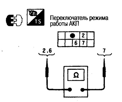
Check continuity between switch contacts.
Between pins 2-7:
- When you turn on the POWER mode: Conductivity is
- In other modes: No conduction
Between pins 6-7:
- When SNOW mode is enabled: Conductivity is present
- In other modes: No conduction
Range switch
1. Moving the selector lever through all ranges, check up conductivity between switch contacts.
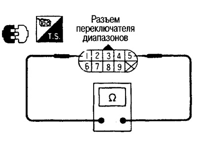 |  |
2. If the result is negative, retest after removing the control cable from the range lever.
3. If after this the conductivity is normal, adjust the control cable.
4. If after that the conductivity between the contacts differs from that given in the table, remove the range switch from the automatic transmission and re-check the conductivity according to the table.
5. If in step 4 the conductivity is normal, adjust the range switch. If the conductivity differs from that shown in the table, replace the range switch.
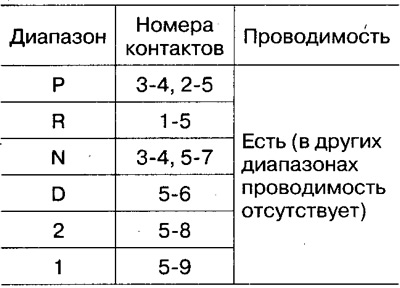
Vehicle speed sensor 1 (automatic transmission secondary shaft speed sensor)
Raise the car, turn the front wheels. There should be battery voltage between pins 1 and 3 of the sensor connector (approx. 12V). The pulse frequency on pin 2 can be measured using the CONSULT tester.
A/B Shift Solenoids, Engine Brake Clutch Solenoid, Line Pressure Control Solenoid, Torque Converter Lockup Clutch Solenoid
Check the resistance between the corresponding terminals of the automatic transmission intermediate wiring connector.
Note: Connect the data cable to the vehicle's diagnostic socket.
- Frequency at 20 km/h: Approx. 455 Hz
Automatic transmission oil temperature sensor
By changing the temperature as shown in the figure, check the resistance between the contacts on the intermediate wiring connector.
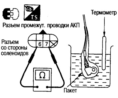
Resistance between pins 6 and 7:
- At a temperature of approx. 20°C: Approx. 2.5 kΣ
- At a temperature of approx. 80°C: Approx. 0.3 kΣ

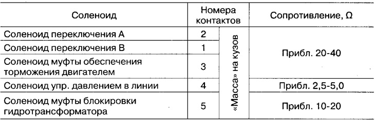
Pull-down resistor
Check the resistance between the pins of the pull-down resistor connector.
- Standard resistance: approx. 12 Σ
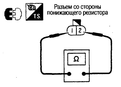
Switch 0/D
Check continuity between tracks 3-4 of the automatic transmission control gear connector.
- O/D ON: No conduction
- O/D OFF: Conductivity is
Note: In the 0/D ON state, the switch contacts are open; in the 0/D OFF state, the switch contacts are closed.
Idle and fully depressed accelerator pedal switch
Check continuity between switch connector pins.
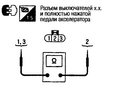
Idle switch (contacts 2-3)
- Accelerator pedal released: there is continuity.
- Accelerator pedal pressed more than half way: no continuity.
Full throttle switch (contacts 1-2)
- Accelerator pedal released: no continuity.
- Accelerator pedal pressed more than half way: there is continuity.
Accelerator sensor
Check the resistance between tracks 2-3 of the sensor connector.
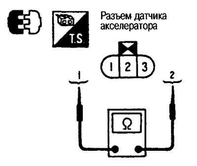
- Accelerator pedal released: approx. 0.8 kΣ
- Accelerator pedal fully depressed: approx. 4.0kΣ
Note: As the pressure on the pedal increases, the resistance also increases.