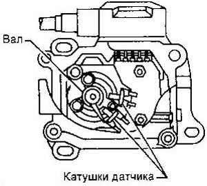
Camshaft position sensor (fault code 11)
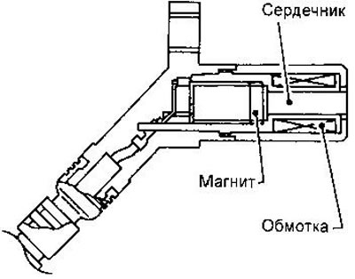
This sensor is located on the injection pump. When the engine is running, the gap between the sensor and the drive shaft periodically changes, and voltage pulses occur in the sensor coil, which are applied to the ECM (4 pulses per 2 revolutions of the crankshaft).
To confirm DTC #11, run the engine for at least 2 seconds. Switch off the ignition and switch it on again after at least 5 seconds. Set diagnostic mode 11 and get a trouble code.
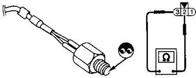
Checking the sensor comes down to inspecting its tip and checking the resistance between pins 2 and 3 of the connector, which should be about 1600 ohms at 25°C.
Coolant temperature sensor (fault code 13)
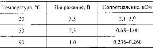
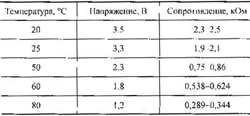
The coolant temperature sensor is a thermistor whose resistance depends on temperature. The supply voltage is applied to the resistor with the ECM.
To confirm DTC #13, turn the ignition on, wait at least 5 seconds, turn the ignition off for at least 5 seconds, and turn it back on. Set diagnostic mode II and get a trouble code.
To check the resistance of the thermistor, unscrew the sensor and lower it into a heated bath of water.
Speed sensor (fault code 14)
The vehicle speed sensor is installed in the gearbox. It contains a pulse generator, the repetition rate of which is proportional to the speed of movement. The signal from the speed sensor is fed to the speedometer, and from it to the engine control unit.
To check the sensor, raise the front of the vehicle and rotate the front wheel to measure the voltage on track 26 of the ECM. The voltage should be in the range of 0-4.2 V (see also chapter «electrical equipment», «instrument cluster»).
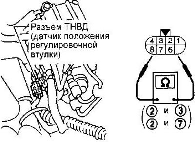
Adjusting sleeve position sensor (fault code 15)
This sensor is installed on the electrical regulator. It monitors the angle of rotation of the sleeve driven in controller movement.
To confirm DTC #15, start the engine for at least 2 seconds, turn the ignition off, wait at least 5 seconds, and turn it back on. Set diagnostic mode II and get a trouble code. To check the sensor, disconnect the injection pump connector and check the resistance between pins 2 and 3, 2 and 7. It should be about 5.8 ohms (at 25°C).
Adjusting resistor (fault code 17)
To confirm the DTC, turn the ignition on for at least 5 seconds, turn it off, wait at least 5 seconds, and turn it on again. Set diagnostic mode II and get a trouble code.
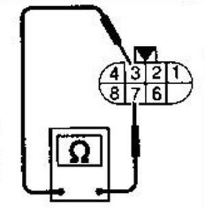
To check the resistor, measure the resistance between tracks 3 and 7 of the injection pump connector. It should lie in the range of 0.2-15.0 kOhm (depends on the number of control sensors). The new adjusting resistor should have the same number as the old one.
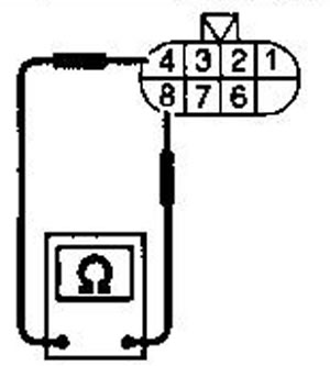
Electric regulator (fault codes 18, 22, 25)
The electric regulator is built into the injection pump. It will move the adjusting sleeve to increase or decrease the fuel supply. The ECM controls the current through the regulator by applying variable duty cycle pulses to it.
To check the regulator, measure the resistance of its winding (pins 4 and 8 of the injection pump connector). It should be about 0.6 ohm (at 25°C).
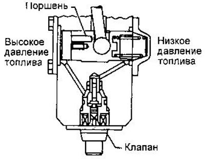
Injection angle control valve (fault code 21)
This valve is built into the injection pump. It controls the position of the piston, which determines the moment of injection. The ECM sends variable duty cycle pulses to the valve.
If DTCs 21 and 34 or 37 are set at the same time, first determine the cause of DTCs 34 or 37. To confirm DTC No. 21, start the engine and increase the speed for 3 seconds to 3000 rpm-1. Reset to idle, then raise again to 3000 min-1 (without load) and turn off the ignition. Wait at least 5 seconds and turn the ignition back on. Set diagnostic mode 11 and get a trouble code.
If the problem occurs intermittently, drive for 10 minutes. This may help determine the DTC.
To check the valve, disconnect its connector and check the resistance between the contacts. It should be around 11 ohms (at 25°C).
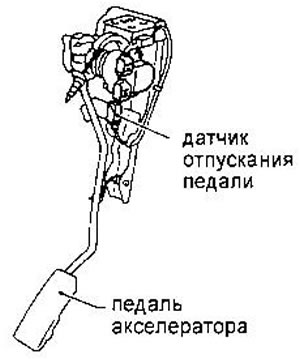
Accelerator pedal release sensor (fault code 23)
This sensor is a switch mounted on the accelerator pedal. Its signal is used by the ECM to cut off the supply and fuel during engine braking.
To confirm DTC No. 23, turn on the ignition and press the accelerator pedal 27 times at 15 second intervals. After that, turn off the ignition, wait at least 5 seconds and turn it on again. Set diagnostic mode II and get a trouble code.
The engine control unit (fault codes 27, 31)
To confirm trouble codes 27 and 31, turn the ignition on for at least 2 seconds, turn it off, wait at least 5 seconds, and turn it back on. Set diagnostic mode II and get a trouble code.
Fan (fault code 28 - overheating)
The ECM controls the fan based on vehicle speed, coolant temperature, A/C pressure, and A/C switch position (ON/OFF). The fan has two rotation speeds.
To prevent this malfunction, it is necessary to fill the cooling system in accordance with the description given in chapter «Maintenance». The coolant must be of the correct composition and filled at a rate of 2 l/min. After filling, make sure that there is no water noise in the system, which indicates the presence of air.
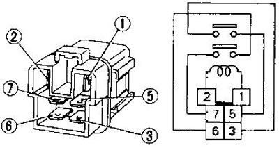
To test the fan relay, apply battery voltage to pins 1 and 2 and verify that pins 3 and 5, 6 and 7 are closed.
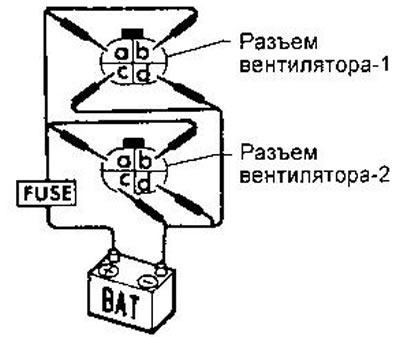
To test the fans, apply battery voltage to their connector pins as follows:
- Low speed - "+" on b, "-" us
- High speed - "+" on a and b "-" on c and d
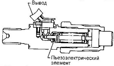
Nozzle needle lift sensor (fault code 34)
This sensor is built into injector #1 and is a piezoelectric element. The sensor is designed to determine the actual injection start time, which may vary depending on the fuel temperature and other factors.
To confirm DTC #34, start the engine and let it idle for 15 seconds. Then turn off the ignition, wait at least 5 seconds and turn it on again. Set diagnostic mode II and get a trouble code.
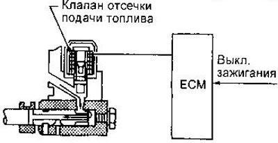
Fuel cut-off valve (fault codes 36, 37, 38)
When the ignition is turned off, the valve is de-energized and closes, interrupting the fuel supply.
To confirm the DTC, start the engine, turn off the ignition for at least 5 seconds and turn it on again. Set diagnostic mode II and better DTC.
To check, turn the valve out and check that its stem rises when 12 V is applied.
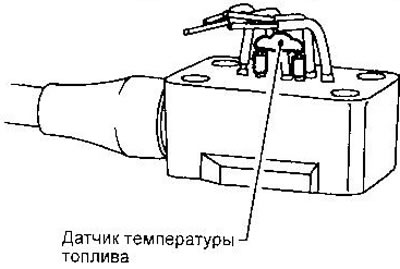
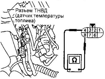
Fuel temperature sensor (fault code 42)
The fuel temperature sensor is a thermistor whose resistance depends on temperature. The supply voltage is applied to the resistor with the ECM. This sensor cannot be removed from the injection pump.
After DTC 43 is confirmed, turn the ignition on, wait at least 5 seconds, turn the ignition off for at least 5 seconds, and turn it back on. Set diagnostic mode II and set the DTC.
To check the resistance of the thermal resistor, measure the resistance between tracks 4 and 8 of the injection pump connector.
Accelerator pedal position sensor (fault code 43)
The pedal position sensor consists of a variable resistor and two limit switches - pedal position sensors.
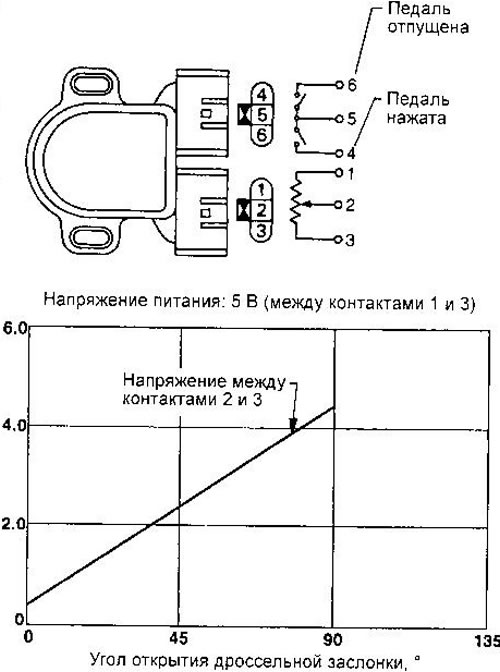
To confirm DTC #43, turn the ignition on for at least 2 seconds, turn it off, wait at least 5 seconds, and turn it back on. Set diagnostic mode II and get a trouble code. With the throttle fully closed, the resistance between pins I and 2 should be about 0.5 kOhm, with the throttle fully open, about 4 kOhm.
WARNING: If the accelerator pedal position sensor or ECM connector has been disconnected, the engine must be started and warmed up, then allowed to idle for 10 minutes.
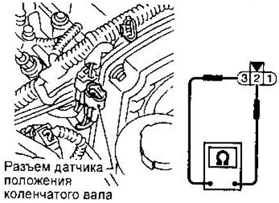
Crankshaft position sensor (fault code 47)
This sensor is used to determine the engine speed. A voltage pulse is generated when a plate with two protrusions attached to the crankshaft pulley passes by the sensor. The moment of occurrence of the impulse corresponds to 70°after TDC. The signal from this sensor is used to control the injection and correct the injection start angle.
To confirm DTC #47, operate the starter for at least 0.5 seconds, start the engine for at least 2 seconds', and turn off the ignition. Wait at least 5 seconds and turn the ignition on again. Set diagnostic mode II and get a trouble code.
To check the sensor, inspect its tip (it should not have chips) and measure the resistance between pins 2 and 3 of the connector. It should lie within 1.215-1.485 kOhm (at 25°C).
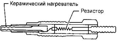
Glow plugs
The quick warm-up system starts working when the coolant temperature is below 75°C. Turning on the ignition, when the ignition key is turned to the ON position, the glow plugs are energized through the glow relay. If the engine has not been started, the glow relay switches off after a certain time, depending on the temperature of the fluid.
Starting: when the starter is turned on, the glow plugs are energized again (if they were turned off). After starting the engine, the spark plugs remain on for a period of time depending on the temperature of the coolant. At a liquid temperature above 50°C, the candles are turned off.
Glow plugs contain a ceramic heating element that can withstand high temperatures.
To test the glow relay, apply battery voltage to its winding and check the closure of the relay contacts.
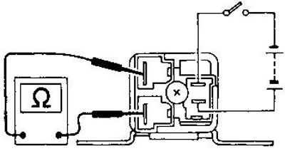
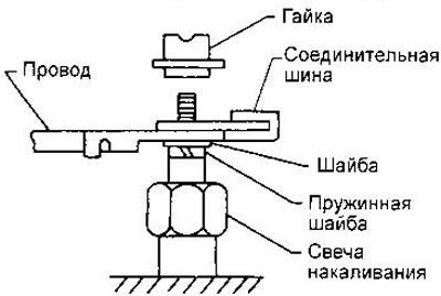
To check the glow plugs, remove the bus connecting the glow plugs and measure the resistance between the output of each candle and ground. It should be about 0.5 ohm (at 25°C).
Install the connecting bar after the measurement.
When working with glow plugs, observe the following instructions:
- Do not shock the heating element. (If the candle has been dropped from a height of more than 10 cm, do not use it.)
- If the glow plug hole is covered with soot, clean it with a suitable tool.
- When installing glow plugs, first tighten them 2-3 turns by hand, then use a torque wrench to finish tightening.
- Tightening torque for glow plugs 15-20 Nm
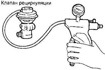
Recirculation control valves A and B, throttle control valve
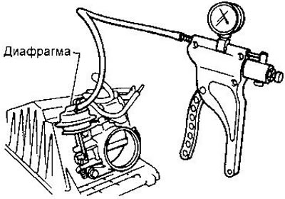
These valves are designed to change the flow of exhaust gases into the intake manifold depending on the temperature of the coolant and the load on the engine. Recirculation control valves A and B determine the vacuum applied to the recirculation valve, which can be closed, half open or fully closed. The throttle control valve regulates the vacuum applied to the throttle actuator diaphragm. By means of a throttle valve, the inlet can be completely blocked (at low engine load) or fully open (at medium and high load).
Thus, with the help of these three valves, a three-stage adjustment of the content of exhaust gases in the air supplied to the cylinders is possible.
To check the recirculation valve, apply a vacuum from a hand vacuum pump to its inlet. The valve diaphragm should rise.
To test the throttle actuator, apply vacuum to the diaphragm chamber inlet. The throttle valve should close.
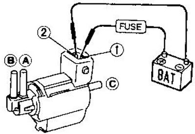
To test the recirculation and throttle control valves, apply battery voltage through the fuse to the connector pins. In this case, the A-B drip should open and the A-C channel should close.