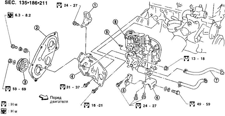
1. Engine lifting eye
2. Back cover
3. Toothed pulley injection pump
4. Bracket injection pump
5. Bracket
6. Bracket
7. Water hoses
8. injection pump
9. Key
Removing
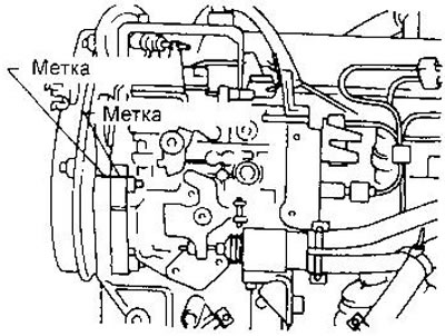
1. Mark the position of the injection pump relative to its bracket.
2. Disconnect a wire of weight from the storage battery, electric sockets and an accelerator cable.
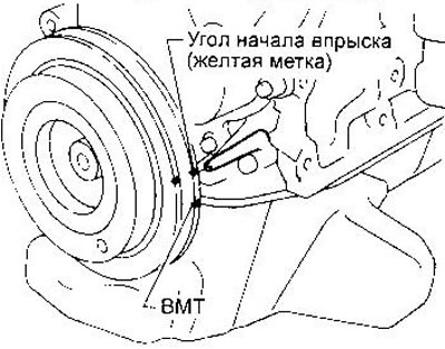
3. Set the piston of the 1st cylinder to the TDC of the compression stroke (notch on the crankshaft pulley without a color mark).
4. Disconnect the cold starter water hoses.
5. Disconnect the fuel lines and fuel supply pipes to the injectors.
6. Remove the air duct and toothed belt cover.
7. Remove the timing belt (see chapter «Engine»).
8. Remove the injection pump timing pulley using a special puller, keeping it from turning with a screwdriver. Do not forget to sleep the key from the injection pump shaft.
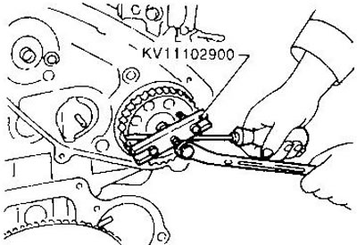
9. Remove the injection pump.
Installation
1. Install the injection pump on the bracket, aligning the marks made during removal.
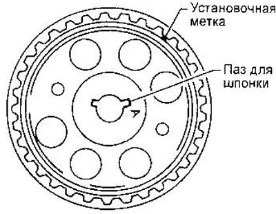
2. Insert the key into the groove of the injection pump shaft, then install the toothed pulley (the keyway is marked as "A").
3. Install the injection pump timing belt (see chapter «Engine»).
4. Adjust the injection start angle.
5. Install all removed parts.
Checking and adjusting the injection start angle
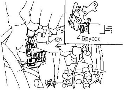
1. Set the cold start device to its normal position:
- a) Rotate the lever of the device clockwise.
- b) Install a bar about 15 mm thick between the plunger and the lever pusher.
- With) Turn the crankshaft 2 turns clockwise.
2. Set the piston of the 1st cylinder to the TDC of the compression stroke (notch on the crankshaft pulley without a color mark).
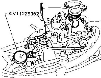
3. Disconnect the fuel supply pipes to the injectors and remove the air release valve at the rear of the injection pump. Install dial gauge with adapter (KV11229352).
4. Set the dial gauge pointer between 1 and 2 mm of the scale.
5. Turn the crankshaft 1 turn clockwise and check that the indicator shows the same value.
6. Rotate the crankshaft counterclockwise 20-25°and set the indicator to zero.
7. By turning the crankshaft, align the yellow injection start mark on the pulley with the pointer (This corresponds to 8°BTDC).
8. Read the indicator readings.
- Plunger lift 0.79-0.85 mm
When remeasuring, start from step a 5.
9. If the plunger lift is not within the specified limits, adjust it by turning the injection pump. Rotate the pump housing away from the engine to increase the lift of the plunger, towards the engine to decrease it.
10. Remove the indicator and install the bleed valve with a new washer. Connect fuel pipes (tightening torque of union nuts - 22-25 Nm).
11. Purge air from the power system (see chapter «Maintenance»).
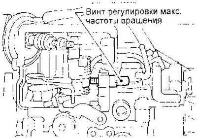
Idle speed and maximum speed adjustment
WARNINGS:
- Do not remove seals unless absolutely necessary.
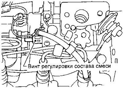
- Do not touch the air mixture adjustment screw, as this may cause engine malfunction.
- Do not set the engine speed when adjusting the engine speed more than the maximum allowable. This may result in engine damage. When connecting the tachometer, remove the fuel pipe clamps (see instructions for the tachometer).
Idle speed adjustment is described in chapter «Maintenance».
Adjustment of the maximum speed is carried out as follows.
1. Start the engine and warm it up until the arrow of the temperature gauge reaches the middle of the scale.
2. Attach the tachometer sensor to the No. 1 injector fuel tube (see instructions for the tachometer).
3. Fully depress the accelerator pedal (gearbox in neutral) and read the tachometer. Maximum speed 5400 min-1.
4. If the tachometer reading is below the specified value, adjust the speed using the adjusting screw.
5. After adjustment, tighten the locknut and close it with a cap.