


Components of the GTZ assembly
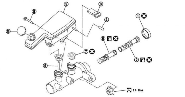
1 - Locking cap; 2 - Primary piston assembly; 3 - Brake fluid level sensor connector; 4 - Clutch hose (models with manual transmission); 5 - Brake fluid reservoir; 6 - Secondary piston assembly; 7 - Gasket; 8 - Screw; 9 - Piston limiter; 10 - Tank cover
1. Drain the brake fluid (see section Replacing brake fluid and bleeding the brake system).
2. Disconnect the brake fluid level sensor wiring connector.
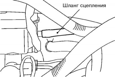
3. On models with manual transmission remove the clutch hose.
4. Using a spanner, disconnect the brake pipes from the master cylinder assembly.
5. Loosen the nuts securing the brake master cylinder assembly and remove it from the vacuum booster.
6. If necessary, carry out repairs related to disassembling and assembling the master cylinder.
7. Secure the brake pipes to the master cylinder by hand.
8. Install the brake master cylinder assembly onto the vacuum booster and tighten the brake master cylinder fasteners with force 14 Nm.
9. Tighten the brake pipes with force 16 Nm.
10. On models with Manual transmission install the clutch hose.
11. Fill and bleed the brake system (see section Replacing brake fluid and bleeding the brake system). On models with manual transmission, bleed the clutch.
(The original is posted on the portal: NISSANBOOK.ru)