1. Entering the self-diagnosis mode
1. Turn the ignition key to position «ON».
2. To enter the self-diagnosis mode, it is necessary within 10 seconds after starting the engine (the ignition key is turned to position «ON») click on the button «OFF» for at least 5 seconds.
Caution: If the battery voltage drops below 12V during Diagnostic Step-3, the damper motor speed will slow down and the system may generate an error even if it is normal. To avoid this situation, start the engine before performing this diagnostic step. Go to step 2.
2. Stage-1: LEDs and display segments are tested
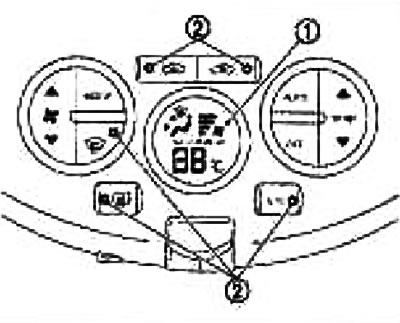
Check display screen (1) and LED lights up (2)
Normal: Go to step 3.
Abnormal: Faulty button «OFF» or automatic controller.
3. Check Progress to Stage-2
Press the temperature control button (▲ up).
Is there progress towards Stage-2?
Yes: Go to step 4.
No: Replace automatic (temperature control button defective).
4. Check return to stage-1
Press the temperature control button (▼ down).
Is there a return to Stage-1?
Yes: Go to step 5.
No: Replace the automatic regulator (temperature control button defective).
5. stage-2: the sensor circuits are checked to detect an open or short circuit.
Press the temperature control button (▲ up).
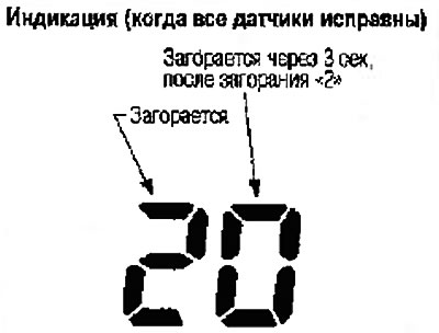
Does the display show a code number «20»?
Yes: Go to step 6.
No: Skip to step 13.
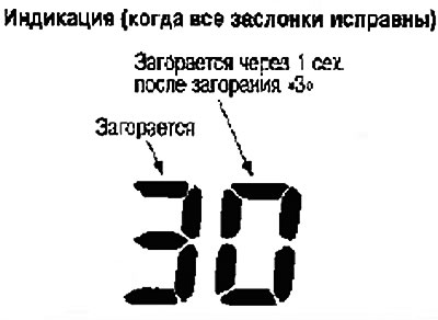
6. Step-3: Mixing damper and fan damper positions are checked
Press the temperature control button (▲ up).
Does the display show a code number «30»?
Yes: Go to step 7.
No: Skip to step 14.
7. Stage 4: check the operation of the motors of all dampers
1. Press the temperature control button (▲ up).
2. Press the button (DEF), The display shows the motor code number of each damper.
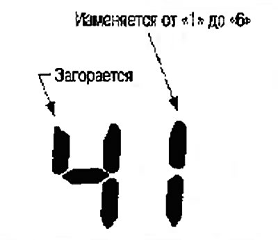
Go to step 8.
8. Check actuators
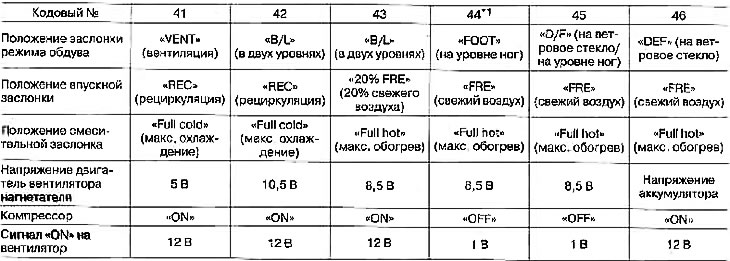
Referring to the table below, check the blowing mode through various air ducts, the temperature of the air supplied to the passenger compartment, the voltage of the blower motor, the operation of the compressor, ionizer and indicator (in mode «ION»).
Airflow mode
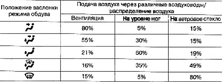
Operation should be checked visually by listening to the sound of operation or by touching the ventilation grilles with your hand
Are the test results OK?
Normal: Go to step 9.
Abnormal: Airflow through certain vents does not change.
The position of the intake flap does not change.
The blower fan motor does not work.
The magnetic clutch does not engage.
The temperature of the air supplied to the passenger compartment does not change.
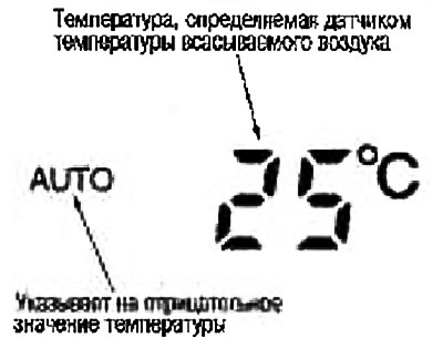
9. Stage-5: The temperature detected by the sensors is checked
1. Press the temperature control button (▲ up).
2. The display shows the code number «5».
Go to step 10.
10. Check ambient temperature sensor
Click once on the button (DEF). The display shows the temperature detected by the ambient temperature sensor.
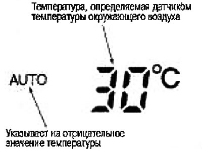
Note: If the temperature shown on the display differs significantly from the actual temperature, check the sensor circuit first and then the sensor.
Are the test results OK?
Normal: Go to step 11.
Abnormal: Defective ambient air temperature sensor.
11. Check the interior air temperature sensor
Click on the button (DEF) a second time. The display shows the temperature detected by the passenger compartment temperature sensor.
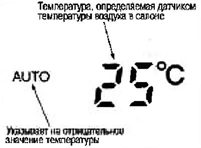
Note: If the temperature shown on the display differs significantly from the actual temperature, check the sensor circuit first and then the sensor.
Are the test results OK?
Normal: Go to step 12.
Abnormal: Faulty interior temperature sensor.
12. Check intake air temperature sensor
Click on the button (DEF) the third time. The display shows the temperature detected by the intake air temperature sensor.
Note: If the temperature shown on the display differs significantly from the actual temperature, check the sensor circuit first and then the sensor.
Are the test results OK?
Fine:
- 1. Turn the ignition key to position «OFF» or click on the button «AUTO» into position «ON»
- 2. End of test
Abnormal: Faulty intake air temperature sensor.
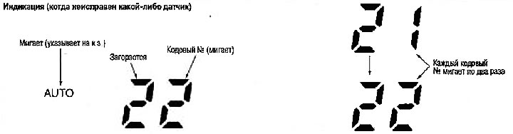
13. Check the faulty sensor
Fault code number, see the table below, (if two or more sensors are faulty, the corresponding code numbers flash 2 times, respectively)
*1: Perform self-diagnosis Stage-2 in bright sunlight.
If self-diagnosis is carried out indoors, direct the light from a flashlight (more than 60 W) to the sunlight intensity sensor. Otherwise, code No. 25 will be displayed, despite the fact that the sensor is working properly.
| Code no | Faulty sensor (including chains) |
| 21 /auto 21 | Ambient temperature sensor |
| 22 /auto 22 | Cabin air temperature sensor |
| 24 /auto 24 | intake air temperature sensor |
| 25 /auto 25 | Sunlight intensity sensor*1 |
| 26 /auto 26 | Potentiometer (PBR) mixing damper motor |
End of check.
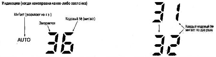
14. Check for defective damper motor position switch
Faulty mixing damper motor or blower damper motor.
Damper Motor Corresponding to the DTC (DTC).
| Code no*1 *2 | 31, 32, 33, 34 | 35, 36, 37, 38 |
| Corresponding damper motor | mixing damper | Air damper |
Fault code (DTC) for faulty wiring.
| Corresponding damper motor | Mixing flap motor | Air damper motor | ||||||
| Corresponding contact (damper motor side) | 3 | 4 | 1 | 6 | 3 | 4 | 1 | 6 |
| Corresponding contact (from the side of the automatic regulator) | 19 | 22 | 21 | 20 | 23 | 26 | 25 | 24 |
| Code number for K.Z. | AUTO31 | AUTO32 | AUTO33 | AUTO34 | AUTO35 | AUTO36 | AUTO37 | AUTO38 |
| Break Code No | 31 | 32 | 33 | 34 | 35 | 36 | 37 | 38 |
(If two mixing dampers or blowing dampers or more are faulty, the corresponding code numbers flash 2 times respectively).
*1: When the connector is disconnected from the mixing flap motor, the display changes in the order: 31→32→33→34→ Return to 31.
*2: When the connector is disconnected from the blower motor, the display changes in the order: 35→36→37→38→ Return to 35.
End of check.