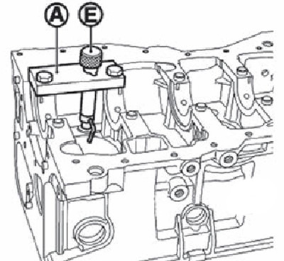
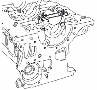
2. Install oil sprinklers for cylinders #1 and #3 as follows:
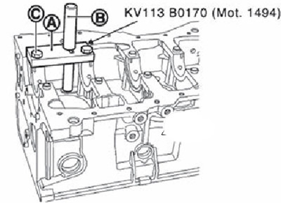
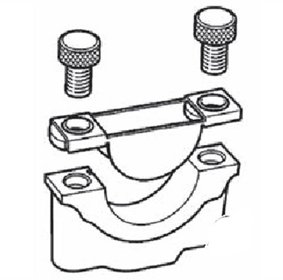
Install plate (A) oil sprinkler puller (special tool: KV113B0170 (Mot. 1494)) into the cylinder block as shown in the figure without tightening the two bolts (WITH).
Place the guide rod (IN) into the plate (A), and insert the end of the guide rod into the oil sprayer hole in the center of the plate (A).
Tighten two bolts (WITH).
Remove guide rod.
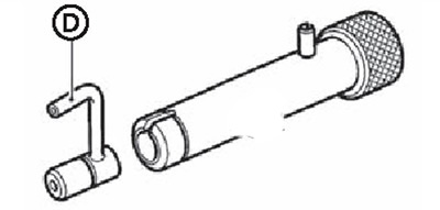
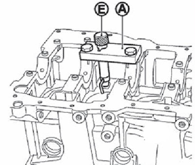
Install the tappet instead of the guide rod, and then insert the oil sprayer into the tappet.
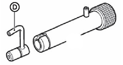
Note. Make sure the oil sprayer (D) correctly directed towards the center of the cylinder.
Tap the pusher with a hammer until the rim (E) pusher will not touch the plate (A).
3. Install the #1 and #4 cylinder oil sprinklers as follows:
Install plate (A) oil sprinkler puller (special tool: KV113B0170 (Mot. 1494)) into the cylinder block (as shown in the figure without tightening the bolts).
Place the guide rod (IN) into the plate (A), and insert the end of the guide rod into the oil sprayer hole in the center of the plate (A).
Tighten two bolts (WITH).
Remove guide rod.
Install the tappet instead of the guide rod, and then insert the oil sprayer into the tappet.
Note. Make sure the oil sprayer (D) correctly directed towards the center of the cylinder.
Tap the pusher with a hammer until the rim (E) pusher will not touch the plate (A).
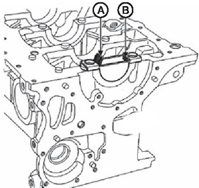
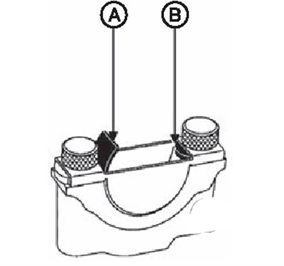
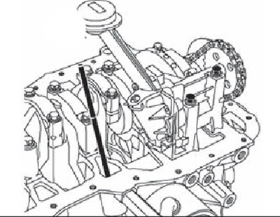
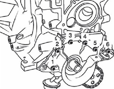
4. Check the direction of the oil sprinklers (see diagram below).
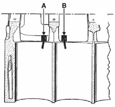
A. The direction of the oil sprayers of cylinders #2 and #4.
B. No.1 and No.3 cylinder oil sprayer direction.
5. Clean the cylinder block and crankshaft by pushing the wire through the oil passages.
6. Install the dipstick guide tube.
7. Select the main bearing bushings as follows:
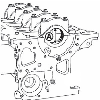
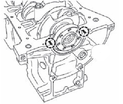
Determine the size group of the crankshaft main journal (A) according to the mark on the balancer, as shown in the figure.
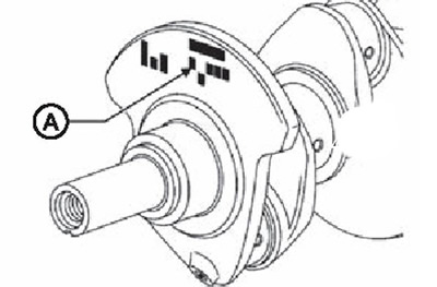
Note. The label has 5 digits. The leftmost number indicates the size group of the main bearings of the neck No. 1 (flywheel side), and the extreme right - the size group of the neck liners No. 5 (sprocket side).
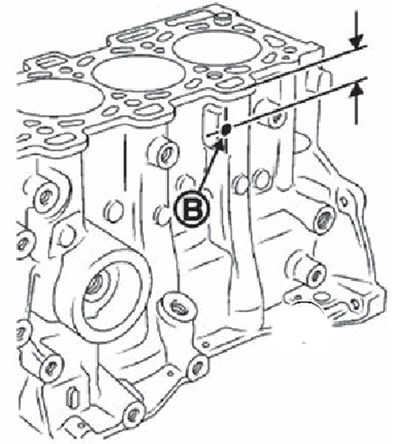
Determine the size group of the bed of the main bearings in the cylinder block (A), while simultaneously measuring the distance from the top surface of the cylinder block to the hole (IN).
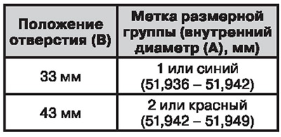 |  |
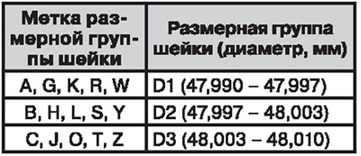
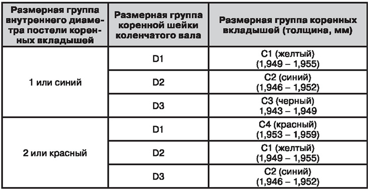
Select the size group of main bearings according to the table.
8. Install the main bearings as follows:
Insert the grooved main bearings into the cylinder block.
Install the plain main bearing covers against the respective main bearings as shown in the illustration.
Install the insert inserter (KV113B0160 (Mot. 1493-01)) to the cylinder block.
Install the bearing cap into the bushing installer (KV113B0160 (Mot. 1493-01)), and then click on the dot (A), until the bearing shell reaches the point (IN).
Place the insertion tool (KV113B0160 (Mot. 1493-01)) in the base cover.
Insert the main bearing into the bearing tool (KV113B0160 (Mot. 1493-01)), and then click at the point (A), until the bearing shell reaches the point (IN).
Lubricate the main bearings with engine oil.
Install the crankshaft.
Install the thrust washers on the No. 3 main bearing, with the recess towards the crankshaft.
Degrease gasket surfaces (cylinder block and main bearing No. 1). They must be clean, dry and free from grease (including without fingerprints).
Apply two beads of sealant 4 mm thick to the No. 1 cylinder bearing.
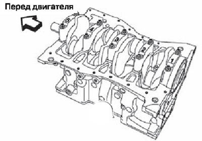
Install the main bearing cover to the No. 1 bearing bushing cover (they are numbered from 1 to 5, with the numbers facing the water pump). Then tighten the main bearing bolts to 25 Nm + tighten by 47°with an angle wrench.
Attention. Check and confirm tightening angle with corner gate (KV10112100) (A) or a transporter. Tightening not recommended «approximately».
9. Check the axial clearance of the crankshaft.
10. Install the connecting rods as follows:
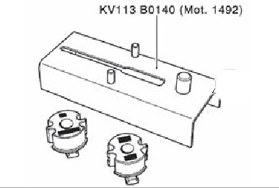
Note. To install the connecting rod bearings, use the connecting rod assembly kit (KV113B0140 (Mot. 1492)) and an adapter for inserts (KV113B0150 (Mot. 1492-03)).
 | 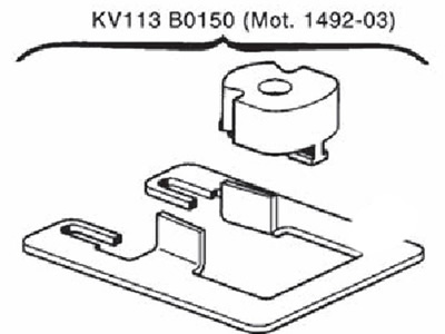 |
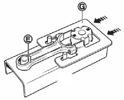
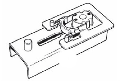
Insert the connecting rod holder (A) adapter for inserts (KV113B0150 (Mot. 1492-03)) (through the notch (IN), shown in the figure) into a groove (WITH) crankset bases (KV113B0140 (Mot. 1492)).
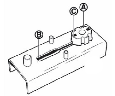
Install guide (D) adapter for inserts (KV113B0150 (Mot. 1492-03)) but the foundation (as shown).
Place the connecting rod but the base of the fixture as shown in the figure. Make sure the bottom (E) the upper head of the connecting rod touches the centering pin, then push the guide (G) in the direction of the arrow.
Put the connecting rod (20.625 mm wide) (F) onto the earbud holder, and then slide it in the direction of the arrow.
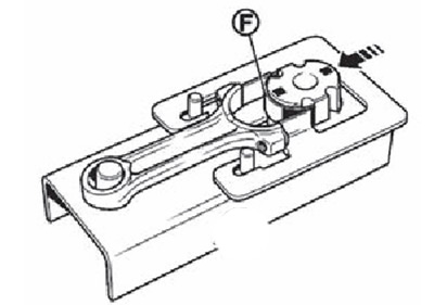
Return the connecting rod holder to its original position.
Remove the connecting rod from the fixture and repeat the operation for the remaining connecting rods.
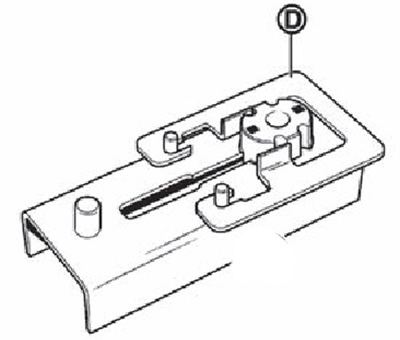
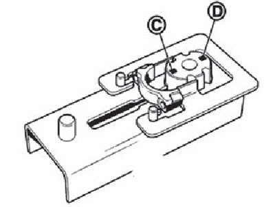
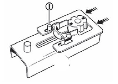
Place the connecting rod bearing holder against the connecting rod cap with the engraved mark (WITH), if the connecting rod bearing width is 20.625 mm, or an engraved mark (D), if the liner width is exactly 17.625 mm.
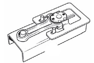
Install the connecting rod cap as shown in the figure.
Push Guide (in the direction of the arrow), until the connecting rod cap touches the pins (I) based on fixture.
Install connecting rod bearing (H) on the earbud holder, and then push it in the direction of the arrow (cook shown).
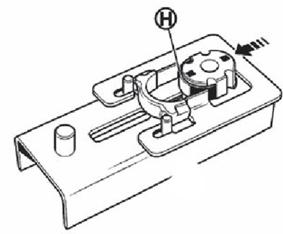
Return the insert holder to its original position on the tool base.
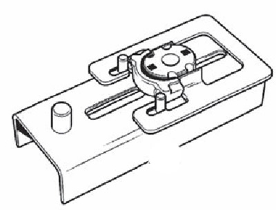
Remove the connecting rod cap from the tool and repeat the operation for the remaining caps.
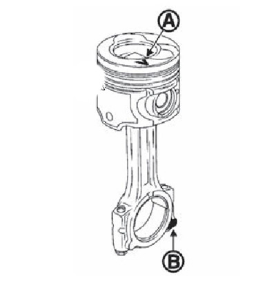
11. Assemble the connecting rods with pistons as follows:
The pistons have marks engraved on the bottom that indicate the direction of the rear of the engine.
Apply engine oil to the piston pin.
Check that the piston pin rotates freely in the piston and its corresponding connecting rod.
Install the piston on the connecting rod so that (A), engraved on the top of the piston head and the lug (IN) but the lower head of the connecting rod at the bottom was on one side, as shown in the figure.
Place a lock (WITH) circlips against the removal/installation groove (D).
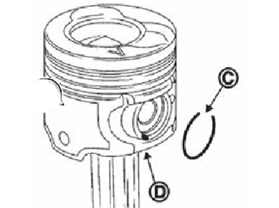
Install retaining rings.
For their correct installation, it is necessary that the rings rotate freely in the piston grooves. Make sure the circlips are installed so that their lock is at the top.
Install the piston rings so that their locks are in the position shown in the figure.
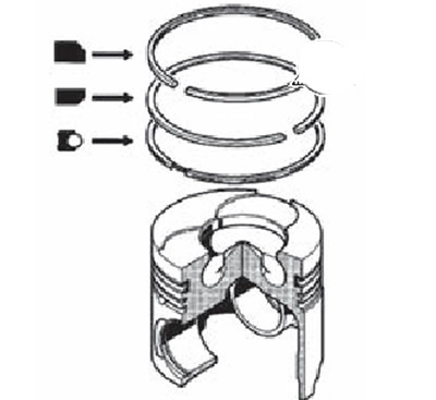
Apply fresh engine oil to the pistons.
Insert the connecting rods with piston assemblies into the cylinder block using a piston ring compressor. When doing this, make sure that the marks on the piston are directed towards the flywheel.
Install the connecting rods on the previously lubricated crankshaft journals.
Install the connecting rod caps to the appropriate connecting rods.
Tighten connecting rod bolts to 20.0 Nm.
Tighten all bolts at 45th clockwise (corner wrench).
Attention. Check and confirm the tightening angle using the angle driver (KV10112100) (A) or a transporter. Tightening not recommended «approximately».
Check the side clearance of the connecting rods.
12. Install the oil pump sprocket and chain.
13. Tighten the oil pump mounting bolts to 25.0 Nm.
14. Install water pump.
Note. Gasket surfaces (block heads and rocker covers) must be clean, dry and free of grease (in particular, even fingerprints must be removed).
15. Press a new oil seal into the crankshaft cover.
16. Install the crankshaft cover and tighten the mounting bolts in the order shown in the figure with a tightening torque of 11.0 Nm.
17. Apply two bead sealant (IN) with a diameter of 5 mm in the places indicated in the figure, as well as two drops of sealant (WITH) with a diameter of 5 mm at the junction of the crankshaft cover and the cylinder block. Use original silicone sealant or equivalent.
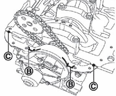
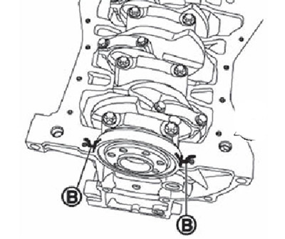
18. Apply two rollers (IN) sealant with a diameter of 5 mm, as shown in the figure. Use original silicone sealant or equivalent.
19. Install the oil pan.
20. Remove excess sealant from the surface of the cylinder block.
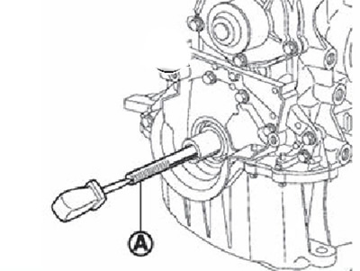
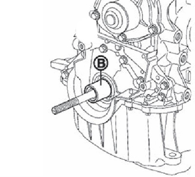
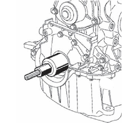
21. Screw in the threaded rod (A) front oil seal kit (KV113B022G (Mot. 1586)) into the crankshaft.
22. Place bushing (IN) front oil seal installation kit (KV113B0220 (Mot. 1586)) like the crankshaft.
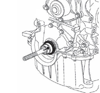
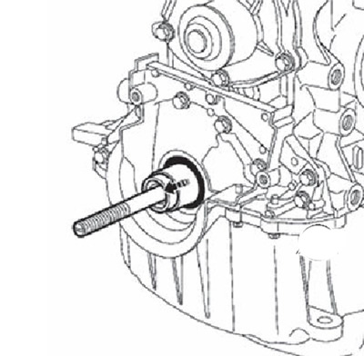
23. Insert the protective kit with gland into the sleeve, being careful that it touches the gland directly.
24. Fit cover (WITH) and a nut (D) (threaded nut (E) must be on the opposite side of the engine) front oil seal kit (KV113B0220 (Mot. 1586)).
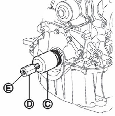
25. Tighten the nut until the cap contacts the bushing.
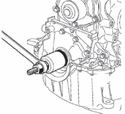 |  |
26. Remove the nut, cap, guard and threaded rod.
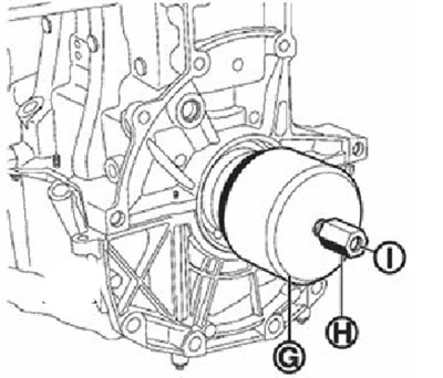
27. Install the crankshaft rear oil seal kit (KV113B0210 (Mot. 1585)) on the crankshaft, fixing it with bolts (F).
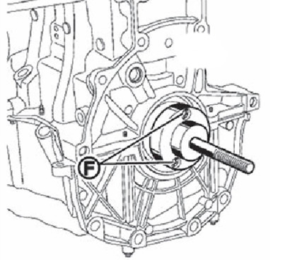
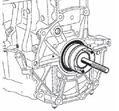
28. Install a protective kit with an oil seal on the kit for pressing the crankshaft rear oil seal (KV113B0210 (Mot. 1585)), being careful not to touch the gland directly.
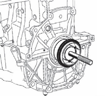
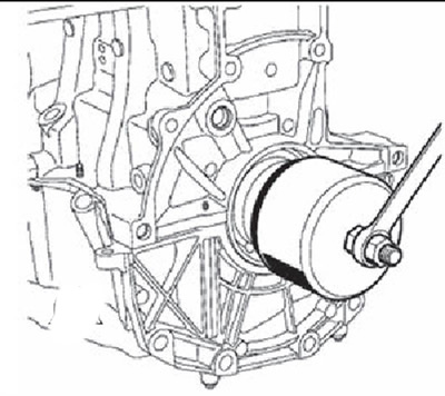
29. Install cover (G) and a nut (H) (threaded nut (I) must be on the opposite side of the engine) crankshaft rear oil seal kit (KV113B0210 (Mot. 1585)).
30. Tighten the nut until the cover touches the cylinder block.
 | 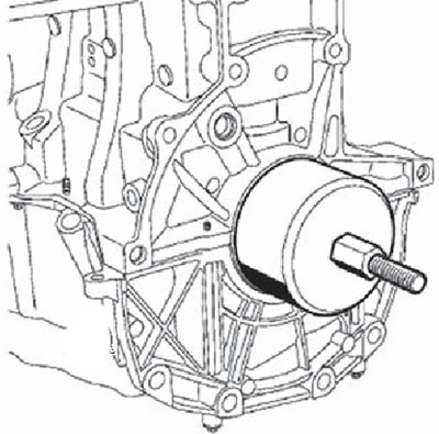 |
31. Remove the nut, cap, guard and threaded rod.
32.Install ring gear retainer (KV113B0060 (Mot. 582-01)) and tighten new flywheel mounting bolts to 20 Nm.
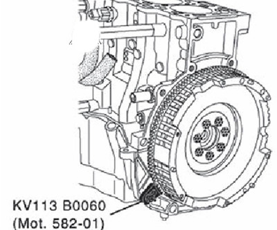
33. Tighten all bolts 36°clockwise (corner wrench).
Attention. Check and confirm the tightening angle using the angle driver (KV10112100) (A) or a transporter. Tightening not recommended «approximately».
34. Install the clutch basket.
35. Remove the flywheel ring gear retainer (KV113B0060 (Mot. 582-01)).