1. Remove the cylinder head cover.
2. Measure valve clearance:
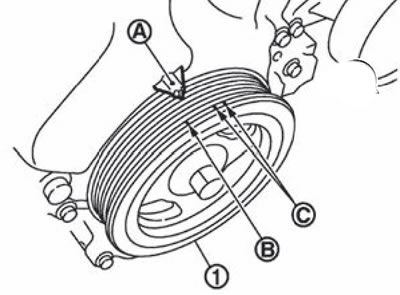
Set the piston of the first cylinder to the position of the top dead center of the compression stroke, for which it is necessary to turn the crankshaft pulley (1) clockwise until the TDC mark is aligned (no color) (IN) with indicator (A) on the front cover.
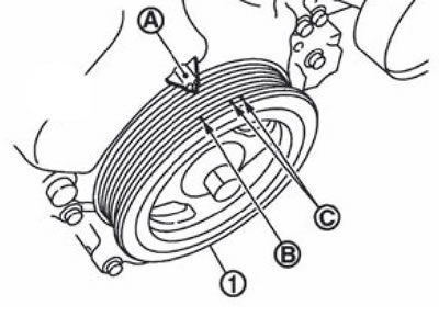
Note. white label (WITH) not used in this procedure.
Make sure the intake and exhaust camshaft lobes for the first cylinder of the engine are pointing up and in (in the direction of the black arrows in the figure).
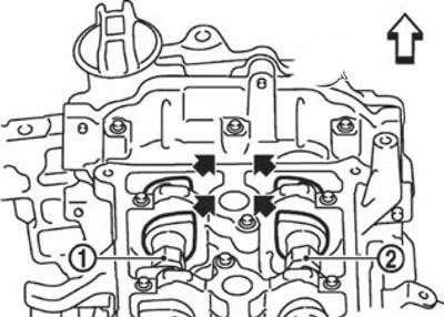
1. Intake camshaft.
2. Exhaust camshaft.
The white arrow points towards the front of the vehicle.
If the lobes do not point in the direction shown, rotate the crankshaft pulley one turn (360°) and align the alignment marks again as described above.
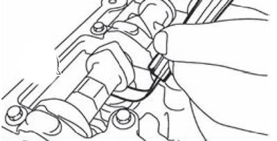
Using a set of feeler gauges, measure the clearance between the valve lifter and camshaft.
Note. Standard valve clearance:
- Inlet: 0.30 mm.
- Release: 0.33 mm.
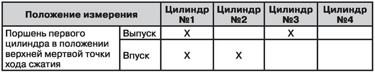
Check the clearances in the valves indicated in the figure below with black arrows or marked in the table «X».
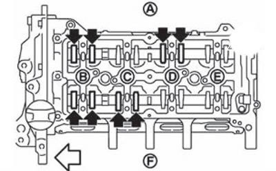
A. Release side.
B. Cylinder #1.
C. Cylinder #2.
D. Cylinder #3.
E. Cylinder #4.
F. Inlet side. The white deal points towards the front of the car.
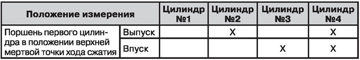
Set the piston of the fourth cylinder to the position of the top dead center of the compression stroke, for which turn the crankshaft pulley (1) for one turn (360°) and align the TDC mark (no color) (IN) with indicator (A) on the front cover.
Note. white label (WITH) not used in this procedure.
Check the clearances in the valves indicated in the figure below with black arrows or marked in the table «X».

A. Release side.
B. Cylinder #1.
C. Cylinder #2.
D. Cylinder #3.
E. Cylinder #4.
F. Inlet side. The white arrow points towards the front of the vehicle.
3. If the values obtained are not correct, perform the gap adjustment procedure.