Note. The gas distribution mechanism of this engine differs from the usual DOHC scheme (two overhead camshafts) with four valves per cylinder, since both the right and left camshafts have both intake and exhaust cams. Refer to the illustration below to locate the intake and exhaust valves.
1. Remove the following parts:
- Oil separator.
- fuel injectors.
- Front engine oil deflector.
- Front cover and timing chain with related parts.
- Fuel pump.
- Vacuum pump.
2. Remove the camshaft position sensor.
Attention.
- Handle the camshaft position sensor with care, do not strike it.
- Do not disassemble the camshaft position sensor.
- Do not expose the sensor to an electromagnetic field.
3. Remove the upper part of the cylinder head:
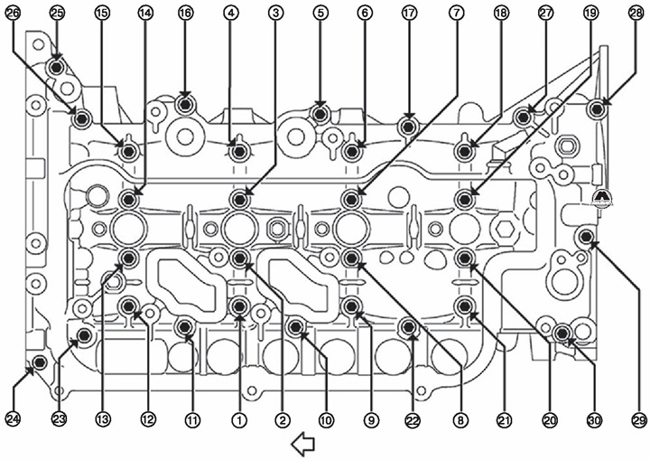
Loosen the mounting bolts in the reverse order to that shown in the figure.
The arrow points towards the front of the engine
Note. The figure shows the sequence of tightening the mounting bolts.
Remove the top of the cylinder head (1), using a flat screwdriver (A) and protective lining (IN).
Attention. Be careful not to damage the mounting surfaces.
4. Remove camshafts:
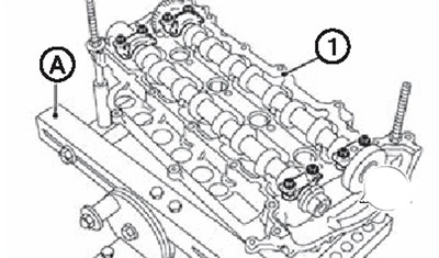
Install the top of the cylinder head (1) on stand for cylinder head (A) (KV113B0200 (Mot.1573 according to Renault catalog)).
Loosen the mounting bolts and remove the main bearing caps and camshafts.
Note. Mark the position of the camshafts and main bearing caps for reinstallation during reassembly.
5. If necessary, remove the fuel pump drive gear from the right camshaft.
Installation
1. Install the fuel pump drive gear (if the eye was removed). Mounting bolt tightening torque: 40.0 Nm + 34°tightening clockwise.
2. Install the camshaft to the top of the cylinder head:
Clean the camshaft journals to remove foreign material.
Install camshafts.
Referring to the figure below, install the camshaft bearing journal covers in their places.
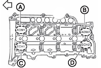
A. Part marked ADM1.
B. Part marked ADM2.
C. Part marked with ECH1.
D. Part marked ECH2. The arrow points towards the front of the engine
Tighten the camshaft main bearing cap bolts by hand.
3. Install the upper part of the cylinder head:
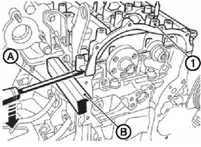
Align the groove of the crankshaft (A) with hole in cylinder block (IN).
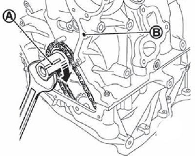
Note. This action is necessary to prevent contact of the valves with the piston crowns.
Completely remove foreign material from the rear of the cylinder head top and cylinder head mounting surfaces.
Apply bead of sealant (A) diameter 0.5-2.5mm on the cylinder head as shown in the figure.
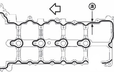
The arrow points towards the front of the engine.
Note. Use original sealant or equivalent.
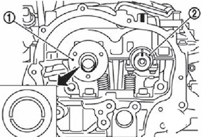
Install the camshafts so that they are in the position shown in the figure: right camshaft groove (1) must be installed so that the protruding part is on top, and the alignment mark of the left camshaft (2) must align with the projection on the cylinder head.
Tighten the cylinder head upper bolts in several stages:
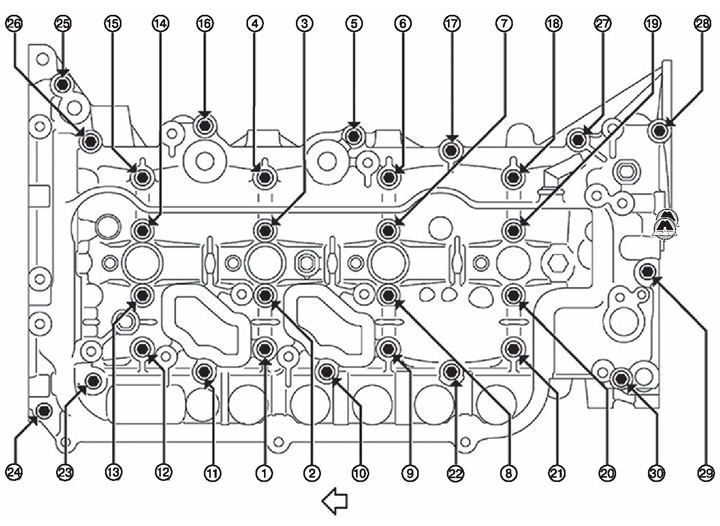
The arrow indicates the side of the front of the engine
Tighten cylinder head top bolts No. 2, 7, 14 and 20 in sequence to evenly seat the top on the cylinder head.
- make money (but don't drag out) remaining bolts.
- Loosen bolts nos. 2,7,14 and 20.
- make money (but don't drag out) bolts No. 2, 7.14 and 20.
- Tighten all bolts in sequence to 5.0 Nm.
- Tighten all bolts in sequence to 12.0 Nm.
Note. After tightening the mounting bolts, remove all excess sealant from the joints of the cylinder head.
4. Install the timing chain and related parts.
5. Install all remaining parts in the reverse order of removal.