Attention! On vehicles with 2.0 liter engine, vehicle model ("Phase I" or "Phase II") can be determined by the shape of the intake manifold. On models "Phase I" the throttle body is mounted on the base of the intake manifold, and the manifold rises up to the cylinder head; the fuel injectors are located on top of the intake manifold and are easily accessible. On models "Phase II" the throttle body is mounted on top of the intake manifold and the manifold drops down to the cylinder head; fuel injectors are less available.
Removing
Models with 1.6L engine
1. Drain the coolant from the cooling system following the instructions in subsection 2.4.5.
2. Perform the operations described in p.p. 1-6 in subsection 6.3.2.10, and disconnect all parts from the throttle body.
3. Note or mark the installation position of all vacuum hoses and intake manifold cooling system hoses. Disconnect them from the intake manifold and, if necessary, from the corresponding vacuum valves. In order not to mix up the hoses during installation, mark each of the hoses when removing.
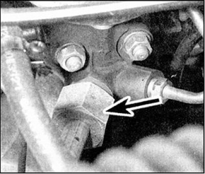
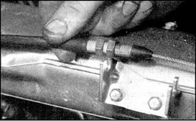
4. Loosen the connection nut (arrow) and disconnect the EGR pipe connecting the intake and exhaust manifolds from the valve on the left side of the intake manifold.
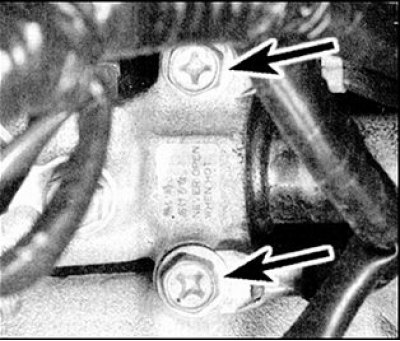
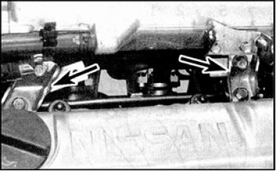
5. Disconnect the connectors from the injectors from the coolant temperature sensor. Get wires from all fixing clips and take away them from an inlet collector. If necessary, unscrew the fixing bolts and disconnect the ground wires (indicated by arrows) from the intake manifold.
6. Remove the mounting bolts and remove the mounting bracket from the bottom of the intake manifold.
7. Release pressure from the fuel system following the instructions in subsection 6.3.2.6, then, release the mounting clamps and disconnect the fuel supply hose and return pipe hose from the left side of the fuel manifold. Plug the hose and fuel rail openings to prevent fuel leakage and dirt from entering the system.
8. Check that all vacuum/vent hoses are disconnected from the intake manifold, then in reverse order to that shown in fig. Intake Manifold Nut and Bolt Tightening Order - 1.6L Models, unscrew and remove the fixing nuts and bolts.
9. Remove the intake manifold from the cylinder head and remove it from the engine compartment, then remove the intake manifold gasket and discard it.
Models "Phase I" with 2.0L engine
10. To improve access, apply the handbrake to the vehicle, then raise the front of the vehicle and support it on stands. The intake manifold and related components can be accessed from above and below the vehicle.
11. Release the mounting clamp and disconnect the intake air line from the throttle body. Disconnect the accelerator cable from the throttle lever, then unscrew the locknut and adjusting nut, and remove the cable sheath from the mounting bracket.
12. Release pressure from the fuel system following the instructions in subsection 6.3.2.6, then, release the mounting clamps and disconnect the fuel supply hose and return pipe hose from the left side of the fuel manifold. Plug the hose and fuel rail openings to prevent fuel leakage and dirt from entering the system.
13. Release the mounting clamps and disconnect the coolant hoses from the throttle body and intake manifold. Quickly plug hose openings to prevent coolant leakage.
14. Note or mark the installation position of all vacuum hoses and intake manifold cooling system hoses. Disconnect them from the intake manifold and, if necessary, from the corresponding vacuum valves. In order not to mix up the hoses during installation, mark each of the hoses when removing.
15. Disconnect the connectors from the throttle potentiometer, air intake control valve, injectors, coolant temperature sensor and air intake control unit when the engine is idling. Remove the wires from the mounting clips.
16. Loosen the mounting bolts and remove the mounting brackets from the left and right sides of the intake manifold.
17. Check that all vacuum/vent hoses are disconnected from the intake manifold.
18. In the reverse order shown in Fig. Intake Manifold Nuts and Bolts Tightening Order - Models "Phase I" with 2.0L engine, unscrew and remove the fixing nuts and bolts of the intake manifold. Note that you may have to remove the oil filter and/or oil filter housing from the rear of the cylinder block to gain access to the intake manifold lower nuts and bolts.
19. Remove the intake manifold from the cylinder head and remove it from the engine compartment, then remove the intake manifold gasket and discard it.
Models "Phase II" with 2.0L engine
20. To improve access, apply the handbrake to the vehicle, then raise the front of the vehicle and support it on stands. The intake manifold and related components can be accessed from above and below the vehicle.
21. Release pressure from the fuel system following the instructions in subsection 6.3.2.6, then, release the mounting clamps and disconnect the fuel supply hose and return pipe hose from the left side of the fuel manifold. Plug the hose and fuel rail openings to prevent fuel leakage and dirt from entering the system.
 |  |
22. Release the mounting clamp and disconnect the intake air line from the throttle body. Disconnect the accelerator cable from the throttle lever, then unscrew the locknut and adjusting nut, and remove the cable sheath from the mounting bracket.
23. Note or mark the installation position of all vacuum and cooling system hoses. Disconnect them from the top section of the intake manifold and throttle body. Quickly plug the holes in the cooling system hoses to prevent coolant leakage. In order not to mix up the hoses during installation, mark each of the hoses when removing.
24. Disconnect the connectors from the throttle potentiometer, auxiliary air control valve, accelerated engine idle solenoid valve and coolant temperature sensor. Remove the wires from the mounting clips.
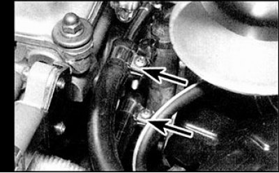
25. Loosen and remove the eight fixing screws fig. The order of tightening the nuts and bolts of the upper section of the intake manifold - models "Phase II" with 2.0L engine and top mounting bracket bolts (indicated by arrows), then remove the top section of the intake manifold along with the throttle body. Remove the gasket and discard it.
26. Disconnect the connectors from the air intake control valve and fuel injectors. Remove the wires from the mounting clips and put them away from the intake manifold.
27. Release the mounting clamps and disconnect the coolant hoses from the throttle body and intake manifold. Quickly plug hose openings to prevent coolant leakage.
28. Remove the mounting bolts and remove the mounting brackets from the back of the intake manifold.
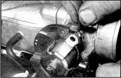
29. Loosen the union nut and disconnect the EGR pipe connecting the intake and exhaust manifolds from the valve on the left side of the intake manifold.
30. Remember or mark the installation position of the hoses. Disconnect them from the lower section of the intake manifold. Quickly plug the holes in the cooling system hoses to prevent coolant leakage. In order not to mix up the hoses during installation, mark each of the hoses when removing. Check that all vacuum/vent hoses are disconnected from the intake manifold.
31. Drain the engine oil and remove the oil filter following the instructions in the appropriate chapter. If the filter was damaged when removed, replace it.
32. In the reverse order shown in Fig. The order of tightening the nuts and bolts of the lower section of the intake manifold - models "Phase II" with 2.0L engine, unscrew and remove the fixing nuts and bolts of the intake manifold. Note that you may have to remove either the oil filter housing from the rear of the cylinder block to gain access to the lower intake manifold mounting nuts and bolts.
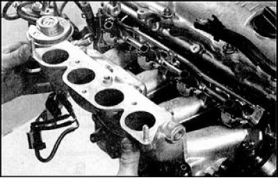 |  |
33. Remove the intake manifold from the cylinder head and remove it from the engine compartment, then remove the intake manifold gasket and discard it.
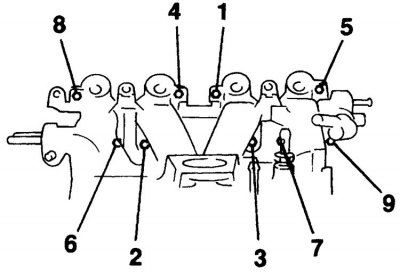
Intake Manifold Nut and Bolt Tightening Order - 1.6L Models
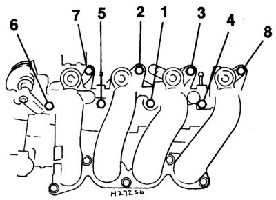
Intake Manifold Nuts and Bolts Tightening Order - Models "Phase I" with 2.0L engine
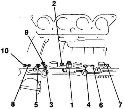
The order of tightening the nuts and bolts of the lower section of the intake manifold - models "Phase II" with 2.0L engine
The order of tightening the nuts and bolts of the upper section of the intake manifold - models "Phase II" with 2.0L engine
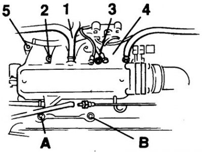
1–5. rear bolts
A–B. Front bolts
Installation
Models with 1.6L engine
1. Installation is carried out in the reverse order of removal. When installing, pay attention to the following points.
2. Check that the mating surfaces of the intake manifold and cylinder head are clean and dry, and install a new gasket on the cylinder head bolts. Install the intake manifold and tighten the mounting nuts and bolts to the correct torque in the order shown in the figure (see fig. Intake Manifold Nut and Bolt Tightening Order - 1.6L Models).
3. Check that all relevant hoses are connected correctly and securely fastened (where necessary) with fastening clamps.
4. Adjust the accelerator cable following the instructions in subsection 6.3.2.3.
5. After installation is complete, add coolant to the cooling system following the instructions in subsection 2.4.5.
Models "Phase I" with 2.0L engine
6. Installation is carried out in the reverse order of removal. When installing, pay attention to the following points.
7. Check that the mating surfaces of the intake manifold and cylinder head are clean and dry, and install a new gasket on the cylinder head bolts. Install the intake manifold and tighten the mounting nuts and bolts to the correct torque in the order shown in the figure (see fig. Intake Manifold Nuts and Bolts Tightening Order - Models "Phase I" with 2.0L engine).
8. Check that all relevant hoses are connected correctly and securely fastened (where necessary) with fastening clamps.
9. Check that the wires of the fuel injection system are correctly located and fastened with the appropriate mounting clips.
10. Adjust the accelerator cable following the instructions in subsection 6.3.2.3.
11. If necessary, fit new O-rings into the recesses of the oil filter housing and install the housing to the cylinder block, tightening the mounting bolts securely.
12. Install the oil filter and fill the engine with engine oil following the instructions in the appropriate chapter.
Models "Phase II" with 2.0L engine
13. Installation is carried out in the reverse order of removal. When installing, pay attention to the following points.
14. Check that the contact surfaces of the lower section of the intake manifold and the cylinder head are clean and dry, and install a new gasket on the cylinder head bolts. Install the lower section of the intake manifold and tighten the fixing nuts and bolts to the required torque in the order shown in the figure (see fig. The order of tightening the nuts and bolts of the lower section of the intake manifold - models "Phase II" with 2.0L engine).
15. Install a new gasket on the lower section of the intake manifold, then, install the upper section of the intake manifold and lightly tighten all the mounting bolts. Tighten the rear mounting bolts securely in the order shown in the figure (see fig. The order of tightening the nuts and bolts of the upper section of the intake manifold - models "Phase II" with 2.0L engine), then securely tighten the three front mounting bolts.
16. Check that all relevant hoses are connected correctly and securely fastened (where necessary) with fastening clamps.
17. Check that the wires of the fuel injection system are correctly located and fastened with the appropriate mounting clips.
18. Adjust the accelerator cable following the instructions in subsection 6.3.2.3. If necessary, fit new O-rings into the recesses of the oil filter housing and install the housing to the cylinder block, tightening the mounting bolts securely.
19. Install the oil filter and fill the engine with engine oil (see subsection 2.2).