2. Drain the coolant.
3. Set the piston of the 1st cylinder to the TDC of the compression stroke.
4. Remove the air filter and cylinder head covers.
5. Release bolts of rollers of yokes.
6. Remove all belts, fan shroud and A/C belt tensioner pulley.
7. Remove the idler pulley.
8. Disconnect the bottom hose of a radiator from a branch pipe and loosen a collar on other end of a branch pipe.
9. Turn away a bolt and remove a branch pipe.
10. Turn away bolts of covers of a gear belt (photo). The bolts should be marked so that they can be installed in their original places during assembly.
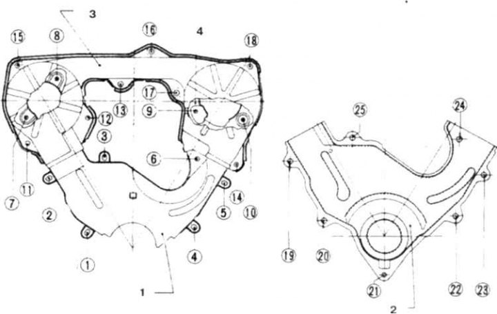
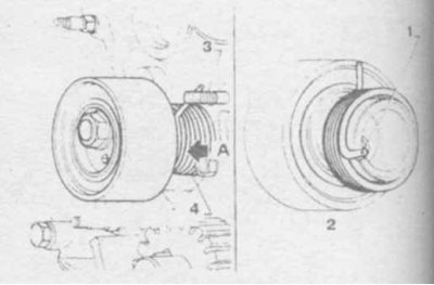
10.10a Timing belt covers
1. Bottom front cover (on 4x2 vehicles); 2. Bottom front cover (on 4x4 vehicles); 3. Top front cover; 4. Back cover
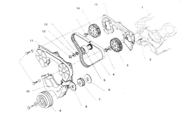
10.106 Toothed belt and drive parts
1. Cylinder block; 2. Mounting pin; 3, 14. Asterisk; 4. Spring; 5. Tensioner; 6,8,13. Washer; 7. Leading sprocket; 9. Pulley; 10,11,15. Lid; 12. Conical washer
11. Make sure all marks on the 3 sprocket are aligned with the fixed pointers (in the form of marks on the belt covers and the pump housing, photo). Otherwise, tighten the crankshaft until the marks are aligned by screwing in the damper bolt.
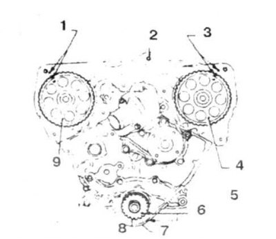
10.11 Alignment marks on belt sprockets
1, 3, 6 marks; 2. Back cover; 4, 9. Left (right) camshaft; 5. The piston of the 1st cylinder is at TDC of the compression stroke; 7. Oil pump; 8. Drive sprocket
12. Loosen the roller nut (photo).
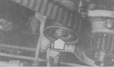
10.12 Tensioner pulley nut
13. Remove the belt. Check the freedom of rotation of the roller (photo).
10.13 Checking the roller
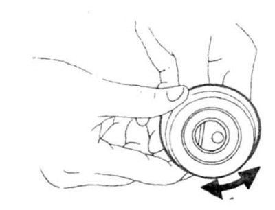
14. Before installing the belt, turn the tensioner clockwise by 70-80°and tighten the lock nut (photo).
10.14 Pre-tensioner adjustment
15. Install the belt so that the arrow points forward.
16. Align the white marks on the belt with the marks on the sprockets (photo).
10.16a Alignment of the belt marks with the marks on the camshaft sprockets.
10.16b Before releasing the locknut, make sure that the mark on the drive sprocket is located opposite the risk on the oil pump housing
Adjustment
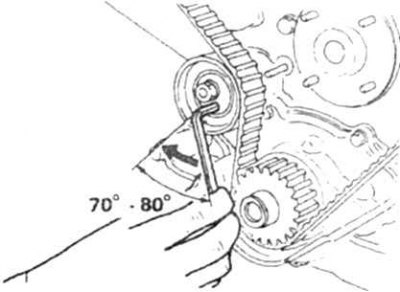
17. Loosen tensioner locknut and turn tensioner 70-80°clockwise again (photo).
10.17 Belt tensioner
1. Hook spring; 2. View along arrow A; 3. Hairpin; 4. Spring
18. Slowly turn the crankshaft clockwise for 2-3 turns and again set the piston of the 1st cylinder to the TDC of the compression stroke. If there is a lot of resistance to rotation, then return the crankshaft to its original position and check the alignment of the belt marks and pulleys.
19. While holding the tensioner, loosen the locknut.
20. Attach a 0.35 mm feeler gauge to the tensioner (photo).
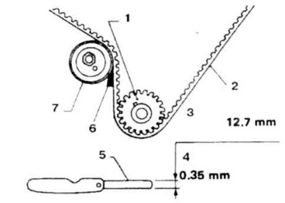
10.20 Place the probe at the indicated location...
1. Crankshaft; 2. Belt; 3. Width 0.500mm; 4. Thickness 0.35mm; 5. Probe; 6. Place of application of the probe; 7. Tensioner roller
21. Slowly turn the crankshaft until the dipstick is between the tensioner and the belt (photo).
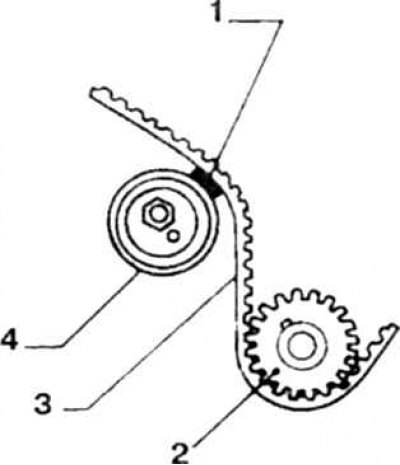
10.21...and rotate the crankshaft until the feeler gauge is between the tensioner and the belt
1. Probe; 2. Crankshaft; 3. Belt; 4. Roller
22. While holding the tensioner, tighten the locknut.
23. Rotate the crankshaft and remove the dipstick.
24. Slowly turn the crankshaft clockwise for 2-3 turns and again set the piston of the 1st cylinder to the TDC of the compression stroke.
25. Check the belt tension according to the diagram (photo).
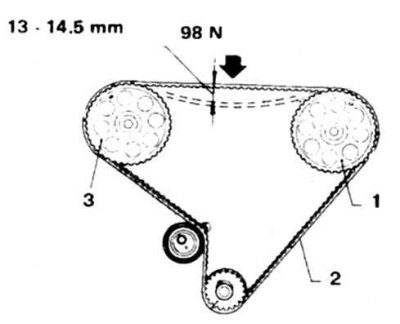
10.25 When checking, apply force in the middle between the sprockets. The deflection must correspond to the specified
1, 2. Camshafts; 3. Belt
26. Install all removed parts.