AT in section
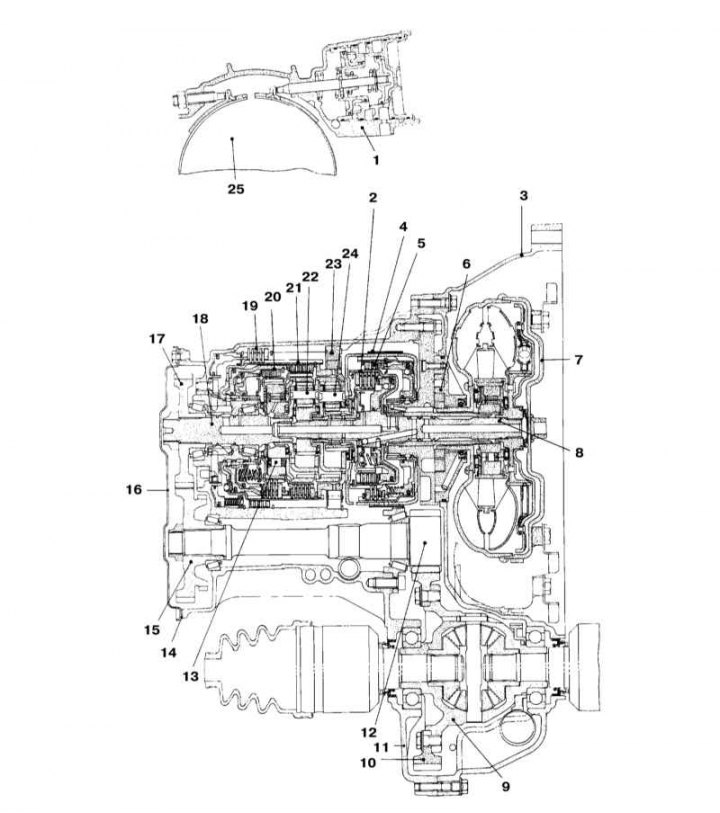
1 - Reinforcing piston of the tape; 2 - High gear clutch; 3 - Torque converter housing; 4 - Brake tape; 5 - Reverse gear clutch; 6 - Oil pump; 7 - Torque converter; 8 - Input shaft; 9 - Differential gear; 10 - Main gear; 11 - Carter AT; 12 - Gear reduction gear; 13 - Freewheel clutch; 14 - Gasket; 15 - Intermediate gear; 16 - Side cover; 17 - Output gear; 18 - Output shaft; 19 - Low gear and reverse gear brake; 20 - Overrunning clutch; 21 - Clutch forward modes; 22 - Planetary reverse gear; 23 - One-way low gear clutch; 24 - Planetary transmission modes of motion forward; 25 - Reverse clutch drum
4-speed AT (RE4F03B) installed on models with engines of 1.2 and 1.4 liters.
During the start of the movement, the AT acts as an ordinary clutch, and when the car is moving, it performs the work of shifting gears.
The main nodes of the AT are: torque converter (torque converter), planetary gear, hydraulic or electronic control units. To switch to another gear ratio in the planetary gearbox, hydraulic disc and band brakes and disc clutches are used.
The torque converter has the same function as a hydraulic clutch. Its task is to carry out the clutch at the start of movement and gear changes. The hydrotransformer is equipped with the blocking coupling which is carrying out direct coupling of the engine with АТ.
AT control system diagram
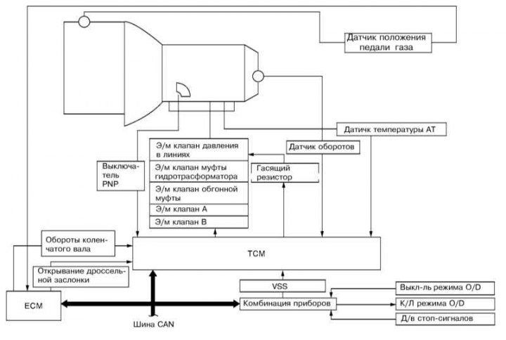
The automatic transmission control system is interfaced with the engine management system via the CAN bus and based on the analysis of data from various information sensors (not necessarily directly related to the functioning of the actual transmission), selects the optimal mode of operation of the AT from the point of view of efficiency, smoothness of switching and other things. AT has its own control unit (TCM). If a malfunction is detected, the corresponding code is written to the memory of the control unit (see Specifications).
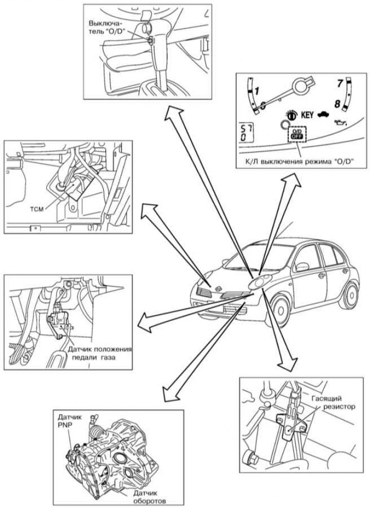
Location of AT control system components
The only AT maintenance procedures that should be performed on a regular basis is checking the level of its working fluid (ATF) and ATF replacement. The procedure for performing these procedures is described in Sections Checking fluid levels, leak control and Replacement of transmission oil AT and manual transmission (respectively).
Thanks to the use of D / V modes «P» / «N» (PNP sensor) the engine can only be started when the AT selector lever is in position «R» or «N», which prevents accidental movement of the car when trying to start.
In the event of their failure of the sensors used by the TCM unit, the AT switches to emergency operation. In this case, the car can only move forward in 4th gear. E/m valves of a gear change are de-energized.
This Chapter provides only general information on the work of AT. More detailed information on the principles of operation and maintenance of the AT can be found in the Manual 179 «Automatic transmissions of modern cars» publishing houses «ARUS».
Scheme of hydraulic lines AT
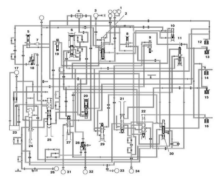
1 - Turn on the torque converter; 2 - Control valve of the torque converter clutch; 3 - Turn off the torque converter; 4 - Tape servo drive; 5 - Control valve; 6 - Valve and piston of the accumulator of gears 1-2; 7 - Filter; 8 - The valve of the moments of a gear change 3-2; 9 - 1st gear pressure reducing valve; 10 - Oil cooler control valve; 11 - Overrunning clutch reducing valve; 12 - E / m pressure control valve in the AT lines; 13 - E / m valve of the torque converter clutch; 14 - E / m overrunning clutch valve; 15 - E / m switching valve B; 16 - E / m switching valve A; 17 - Oil pump; 18 - Accumulator for turning off the servo; 19 - Torque converter bypass valve; 20 - Pressure modulation valve; 21 - Switching valve B; 22 - Switching valve A; 23 - Oil intake; 24 - Manual valve; 25 - Pressure control valve; 26 - Reverse gear clutch; 27 - Overrunning clutch control valve; 28 - Accumulator modes «N» And «D»; 29 - Accumulator control valve; 30 - Spool control valve; 31 - Overrunning clutch; 32 - Clutch forward modes; 33 - Brake 1st gear and reverse gear; 34 - High gear clutch
The design of the gear shift mechanism
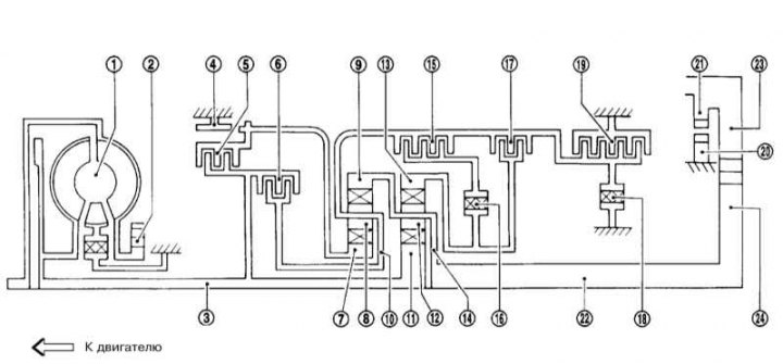
1 - Torque converter; 2 - Oil pump; 3 - Input shaft; 4 - Brake tape; 5 - Reverse gear clutch; 6 - High gear clutch; 7/8 - Central / small gear wheel of the forward drive; 9 - Toothed wheel of internal gearing of forward motion transmission; 10 - Planetary transmission of forward motion transmission; 11/12 - Central / small gear wheel of the reverse gear; 13 - Gear wheel of internal gearing of the reverse gear; 14 - Planetary reverse gear; 15 - Forward clutch; 16 - Freewheel clutch; 17 - overrunning clutch; 18 - One-way low gear clutch; 19 - Low gear and reverse gear brake; 20 - Parking mode fuse; 21 - Parking mode gear; 22 - Output shaft; 23 - Intermediate gear; 24 - Output gear
List of components involved in AT modes (part numbers correspond to illustration numbers)
Mode | 5 | 6 | 15 | 17 | Belt servo | 16 | 18 | 19 | blocking | |||
2nd incl. | 3rd off | 4th incl. | ||||||||||
| P | ||||||||||||
| R | O | O | ||||||||||
| N | ||||||||||||
| D*4 | 1 | O | *1 D | B | B | |||||||
| 2 | O | *1 A | O | B | ||||||||
| 3 | O | O | *1 A | *2 C | C | B | *1 O | |||||
| 4 | O | C | *3 C | C | O | O | ||||||
| 2 | 1 | O | O | B | B | |||||||
| 2 | O | O | O | B | ||||||||
| 1 | 1 | O | O | B | O | |||||||
| 2 | O | O | B | |||||||||
1 - Works when the mode switch «O/D» is in position «OFF».
*2 - Oil pressure applied simultaneously to the sides «2nd included» And «3rd off» reinforcing piston tape.
*3 - Oil pressure applied to side «4th included» provided *2.
*4 - AT will not shift to 4th gear when the mode switch «O/D» is in position «OFF».
A - Works when the throttle is open no more than 3/16, engine braking is activated.
B - Works with strong acceleration.
C - Works, but does not affect power transmission.
D - Works when the throttle is open no more than 3/16; has no effect on power transmission.