Removing
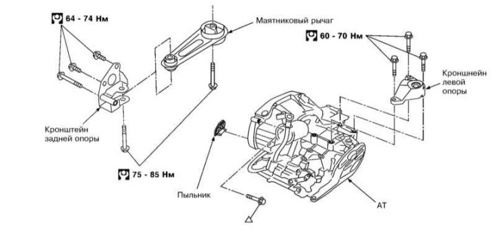
AT mounting components
1. Remove the battery (see chapter Engine Electrical Systems) and air duct (see chapter Power supply and exhaust systems).
2. Remove breather hose and CKP sensor (see Section The principle of operation of the engine management system).
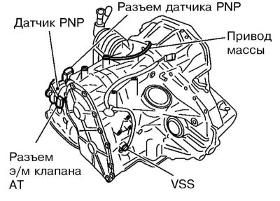
3. Disconnect the wiring of the PNP sensor, the valve solenoid, the VSS sensor and the ground wire.
4. Remove the selector cable from the AT.
5. Remove the front section of the exhaust pipe (see chapter Power supply and exhaust systems).
6. Remove drive shafts (see chapter Drive shafts, steering knuckles and hub assemblies).
7. Remove the oil cooler hose.
8. Remove the starter (see chapter Engine Electrical Systems).
9. Remove the anther from the torque converter housing (see illustration AT mounting components).
10. Turning a cranked shaft, turn out 4 bolts of fastening of a driving disk and the hydrotransformer.
11. Establish a jack under АТ.
12. Remove the bracket for the rear engine mount and the pendulum lever, and also unscrew the bolts securing the AT to the bracket for the left engine mount (see chapter Engine).
13. Place a jack under the engine.
14. Turn out bolts of fastening АТ to the engine and remove АТ.
Installation
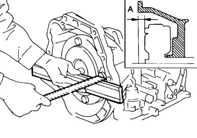
1. Make sure that the distance between the torque converter and the end of its housing is at least 21.1mm.
2. Establish the hydrotransformer on a driving disk and turn a cranked shaft on some turns to make sure of smoothness of the course of АТ.
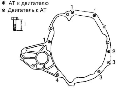
3. Tighten the AT fastening bolts: bolts No. 1 (50 mm) and #2 (135 mm) - with effort 31÷40 Nm, and bolts No. 3 (20 mm) and #4 (30 mm) - with effort 17÷23 Nm.
Note. The bolts have different lengths, do not mix them up.
4. Install all removed components.
5. After installation, adjust the selector cable (see Section Selector cable adjustment), correct the ATF level and check for leaks. Check the correct operation of the AT.