Input shaft
Disassembly, inspection and assembly of the input shaft are completely similar to the operations of the same name for the input shaft of gearboxes RS5F30A and RS5F31A.
Output shaft
Disassembly
The disassembly of the output shaft has the following features compared to the RS5F30A/31 A gearboxes. After measuring the axial clearance of the gears, remove the rear bearing circlip, half ring holder and half ring. Then press the rear bearing with a universal puller and remove the spacer. Further disassembly is carried out in the same way as in gearboxes RS5F30A/31A.
Examination
The main difference between the RS5F30A/31A and RS5F32A gearboxes is the design of the 2nd and 3rd gear synchronizers, so only checking the synchronizers is described here. Checking the remaining parts of the output shaft is carried out in the same way as for gearboxes RS5F30A/31A.
WARNING: The output shaft front bearing must be replaced with a new one each time. The bearing must not be reused.
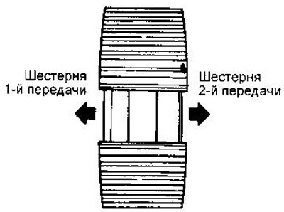
Synchronizers. Measure the gap between the synchronizer blocking ring and the gear ring (for synchronizers of 1st and 4th gears).
Rated Clearance:
- Synchronizer 1st gear - 0.95-1.45 mm
- Synchronizer 4th gear - 0.90-1.45 mm
The maximum allowable gap is 0.7 mm.
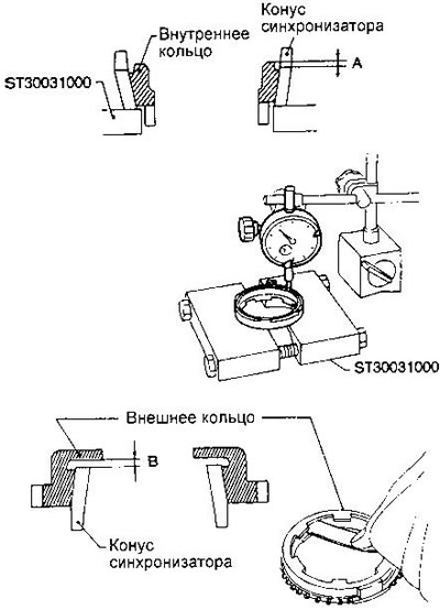
Check the degree of wear of the blocking rings of the synchronizers of the 2nd and 3rd gears as follows.
Install the inner blocking ring in the synchronizer cone.
Align the ring with the cone and measure distance A.
Install the outer blocking ring on the synchronizer cone.
Align the ring with the cone and measure distance B.
Rated values:
- A (inner ring) - 0.7-0.9 mm
- IN (outer ring) - 0.6-1.1 mm
Limit wear - 0.2 mm.
If distance A or B is less than the limit, replace the blocking ring.
Assembly
1. Install the needle bearing, driven gear and 1st gear synchronizer ring.
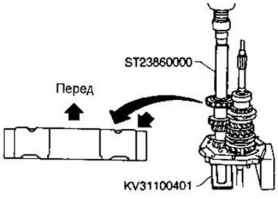
2. Press on the 1st and 2nd gear synchronizer hub using tool ST22452000. The hub must be located in a certain way relative to the shaft.
3. Install the 2nd synchronizer cone, outer and inner races, reverse driven gear (synchronizer clutch).
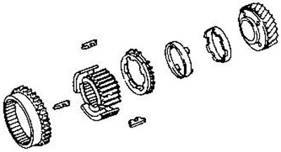
4. Install the steel ball, 2nd driven gear, and 2nd and 3rd gear hub.
Lubricate the bushing with gear oil before installing.
Before installing the ball, apply multipurpose grease to the ball. The sleeve has a groove into which the ball must fit.
5. Install 3rd driven gear, synchronizer cone, outer and inner races.
6. Press on the 3rd and 4th gear synchronizer hub using tool ST22452000. The hub must be located in a certain way relative to the shaft.
7. Install the 3rd and 4th gear synchronizer clutch and the 4th gear synchronizer ring.
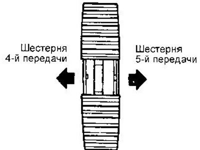
8. Install the steel ball, bushing and 4th driven gear.
Before installing the ball, apply multipurpose grease to the ball.
The sleeve has a groove into which the ball must fit.
9. Press the 5th driven gear onto the shaft using tool ST37750000.
10. Pick up the output shaft bearing spacer.
- Size C - 230.15-230.25 mm
Available bushings are listed in section «Data for adjustments and control».
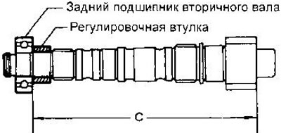
11. Press the rear bearing onto the shaft using tool ST37750000.
12. Pick up the half-rings included in the groove of the shaft with a gap of 0-0.1 mm. Available ring thicknesses are listed in section «Data for adjustments and control».
13. Install the half-ring holder and retaining ring.
14. Measure the axial clearance of the gears.