Note. All directions of rotation appearing in the text are assumed when looking at the engine from the front.
1. Remove the front right wheel.
2. Remove the front right fender liner.
3. Drain engine oil.
Attention. Drain the engine oil only after the engine has cooled down.
4. Remove the following parts:
- Intake manifold.
- Cylinder head cover.
- Attachment drive belt.
5. Set the piston of the first cylinder to the position of the top dead center of the compression stroke:
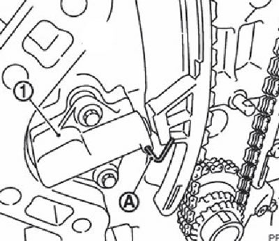
Rotate the crankshaft pulley (1) clockwise until the TDC mark is aligned (no color) (IN) with indicator (A) on the front cover.
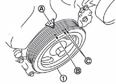
Note. white label (WITH) not used in this procedure.
Make sure the intake and exhaust camshaft lobes for the first cylinder of the engine are pointing up and in (in the direction of the arrows in the figure).
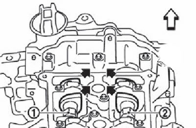
1. Intake camshaft
2. Exhaust camshaft.
The white arrow points towards the front of the vehicle.
If the lobes do not point in the direction shown, rotate the crankshaft pulley one turn (360°) and again combine the set marks in the manner described above.
6. Remove the crankshaft pulley:
Fix the crankshaft pulley (1) fixative (A) and unscrew the bolt from the pulley by 10 mm.
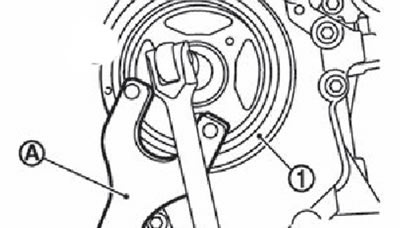
Note. Do not completely unscrew the crankshaft pulley bolt, as it will still be needed as an opera point for the pulley puller (KV11103000).
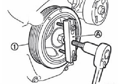
Install pulley puller (A) (KUP 103000) into the threaded holes MB in the pulley (1) and remove the crankshaft pulley
7. Remove the rear engine tie rod.
8. Support the underside of the engine with a transmission jack, then remove the engine mounts and right engine mounting insulator.
9. Remove the lower oil pan.
Note. If you do not intend to remove the crankshaft sprocket and balancer assembly components, this step is not necessary.
10. Remove the oil supply solenoid valve to the intake valve timing control system.
11. Remove the automatic attachment drive belt tensioner.
12. Remove the engine front cover:
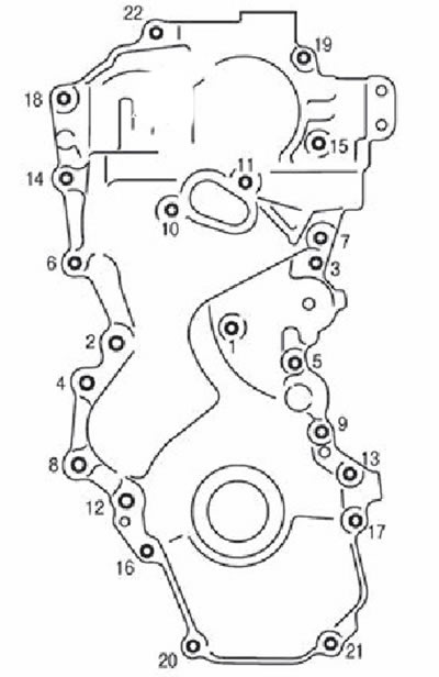
Loosen the mounting bolts in the reverse order as shown in the figure.
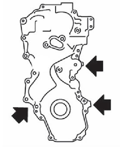
Separate the parts by inserting the caulk cutter into the places indicated by the arrows in the figure, and then remove the front cover,
Attention.
- Be careful not to damage the contact surfaces.
- Sealant has been applied in some places to meet certain operational needs and does not need to be removed, so the sealant only needs to be cut at the points shown in the figure.
13. Use a screwdriver to remove the front oil seal from the front cover.
Attention. Be careful not to damage the front cover.
14. Remove the timing chain tensioner:
- Press the plunger of the timing chain tensioner.
- Insert locking pin (A) into the hole in the body and fix the plunger in the depressed position.
Note. Use a hard metal rod with a diameter of about 1.5 mm.
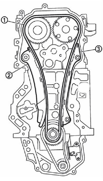
Remove the timing chain tensioner (1).
15. Remove tensioner guide (2), sedative (3) and drive chain (1).
Attention. Do not turn the crankshaft and camshafts separately from each other with the timing chain removed. This can cause the pistons to come into contact with the valves and damage them as a result.
16. Remove the crankshaft sprocket and balancer block drive components:
Fully raise the lever (A) and press the drive chain guide (IN) inside the balancer block drive chain tensioner (1).
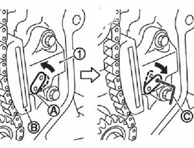
Note. The drive chain guide is unlocked when the lever is fully raised, so that it can be moved.
Align the hole in the arm with the hole in the tensioner housing and insert the locking pin (WITH) to secure the guide.
Note. Use a hard metal rod with a diameter of approximately 1.0 mm as the locking pin.
Remove the balancer block drive chain tensioner.
Note. If the holes in the arm and tensioner housing do not line up, align them by slightly moving the chain guide.
Holding the cylindrical part (A) balance shaft (width of the cylindrical part: 19.0 mm), unscrew the balance shaft sprocket bolt.
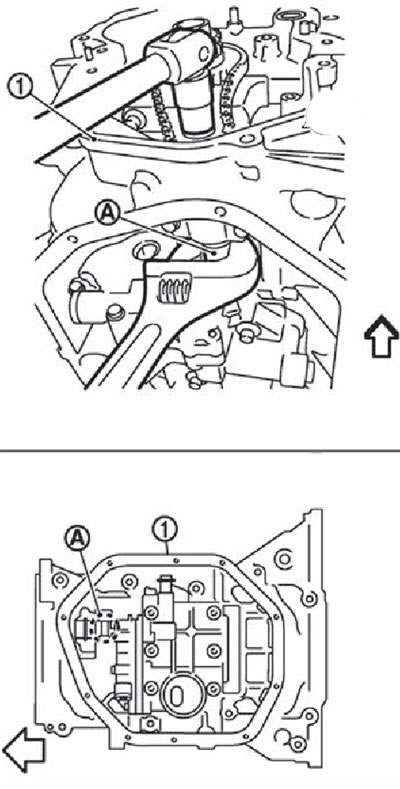
1. Upper oil pan. The arrow points to the front of the engine.
Remove the crankshaft sprocket, sprocket and balancer drive chain 6 in one set.
17. Remove the timing chain guide from the front cover, if necessary.