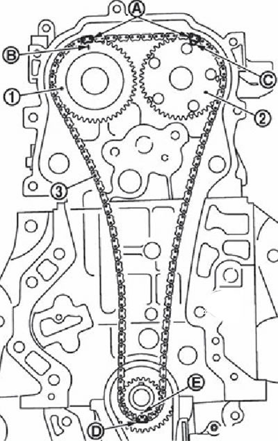
Note. The figure shows the relative position of the timing marks on the drive chains and the corresponding sprockets with the components installed.
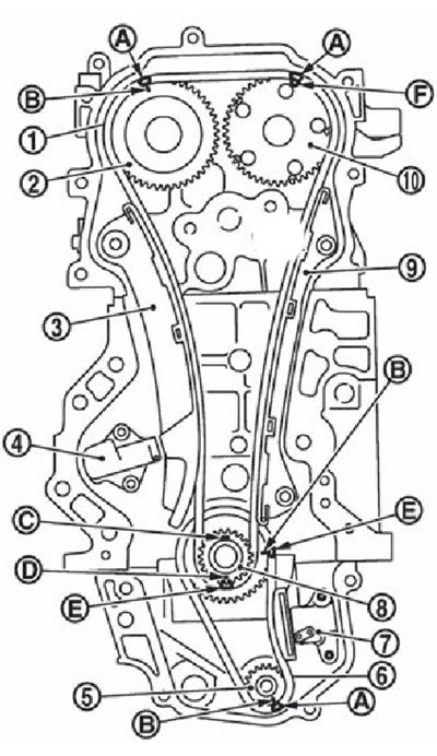
1. Timing chain drive.
2. An asterisk of a final camshaft.
3. Timing chain tensioner guide.
4. Timing chain tensioner.
5. Asterisk of the balancing block.
6. Balancing block drive chain.
7. Chain tensioner drive balancing block.
8. Crankshaft sprocket.
9. The damper of the timing chain drive.
10. Intake camshaft sprocket.
A. Installation mark (dark blue link).
B. Installation mark (stamp).
C. Crankshaft key position (vertically up).
D. Reference mark (stamp).
E. Installation mark (orange link).
F. Reference mark (outer groove - there are two outer grooves on the intake camshaft sprocket, the wider one is the alignment mark).
1. Make sure the crankshaft key is installed vertically up.
2. If the drive chain guide is removed from the front cover, install it on the front cover.
3. Install the crankshaft sprocket (2), balancing block sprocket (3) and drive chain of the balancing block (1):
A. Installation mark
B. Installation mark (orange link).
C. Installation mark (dark blue link).
Install the chain and sprockets, aligning the alignment marks accordingly.
If the alignment marks do not match, turn the balance shaft slightly to correct the position.
Attention. After installing the drive chain of the balancing block, you must once again check the coincidence of all installation marks.
4. Holding the cylindrical part (A) balance shaft (width of the cylindrical part: 19.0 mm), tighten the balance shaft sprocket bolt.
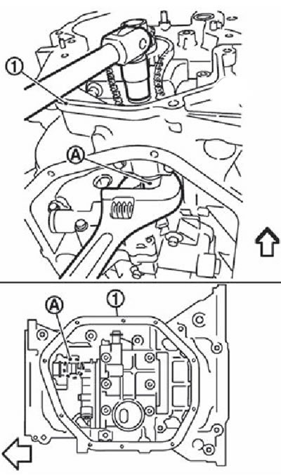
1. Upper oil pan. The arrow points towards the front of the engine.
Attention. Only hold the balance shaft at the cylindrical part. Do not tighten the balancing block sprocket bolt while tensioning the drive chain.
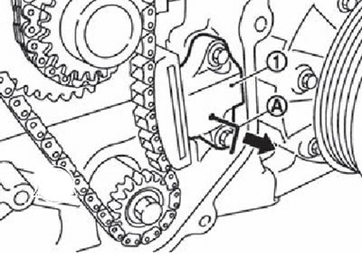
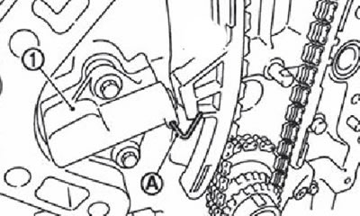
5. Install the balancer block drive chain tensioner (1):
Lock the plunger in the maximum compression position using the locking pin (A), and install the tensioner, (www.monolith.in.ua)
After the tensioner is in place, carefully remove the locking pin (in the direction of the arrow in the figure).
Recheck the position of the alignment marks of the drive chain of the balancing block and sprockets.
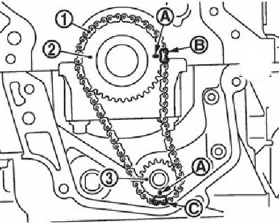
6. Align the timing marks on each sprocket with the timing marks on the drive chain.
1. An asterisk of a final camshaft.
2. Intake camshaft sprocket. 3.
Timing chain drive.
A. Installation mark (dark blue link).
B. Installation mark (stamp).
C. Installation mark (outer groove - there are two outer grooves on the intake camshaft sprocket, the wider one is the alignment mark).
D. Reference mark (orange link).
E. Installation mark (stamp).
Note. If the timing marks do not match, slightly turn the camshaft at the hex part to correct the position.
Attention. After installing the drive chain, check again the position of the timing marks on each sprocket and on the chain.
7. Install the chain guide (3) and tensioner guide (2).
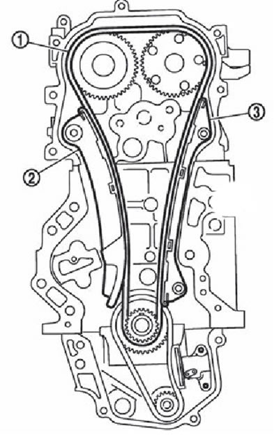
1. Timing chain drive.
2. Chain tensioner guide.
3. Chain guide.
8. Install the timing chain tensioner (1):
Lock the plunger in the maximum compression position using the locking pin (A), and install the tensioner.
After the tensioner is in place, carefully remove the locking pin.
9. Again check the position of the alignment marks on the sprockets and the drive chain.
10. Install the front oil seal.
11. Install the front cover:
Install a new O-ring to the cylinder block.
Attention. Make sure that the O-ring is installed without distortion.
Apply a continuous bead of sealant with a gun (IN) on the front cover as shown in the figure.
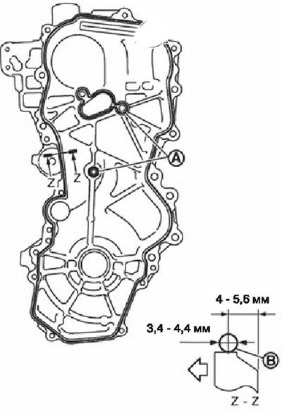
A. Sealant application areas.
B. Sealant bead.
The arrow points to the outside of the engine.
Note. Use original sealant or equivalent.
Verify that the timing marks on each sprocket and drive chains still line up. Install the front cover.
Attention.
- Make sure the O-ring is installed correctly in the cylinder block.
- Be careful not to damage the front oil seal with the front of the crankshaft.
Install the front cover and tighten the mounting bolts in the order shown in the figure.
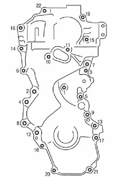
Note. The following bolt sizes are used to fasten the front cover:
- M6: No. 1
- M10: Nos. 6, 7, 10, 11, 14
- M12: Nos. 2, 4, 8, 12
- M8: all others.
Attention. Installation should be done within five minutes of applying the sealant.
Tighten all bolts in the order shown in the figure to the specified tightening torque.
Attention. Remove any spilled excess sealant.
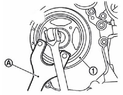
12. Install the crankshaft pulley.
Install the crankshaft pulley by tapping on its center (not around the circle) plastic hammer.
Attention. Be careful not to damage the outer edges of the seal.
Fix the crankshaft pulley (1) holder (A).
Apply fresh engine oil to the threads and seating surfaces of the crankshaft pulley bolt.
Tighten the crankshaft pulley bolt to 68.6 Nm.
Completely unscrew the pulley bolt.
Tighten the crankshaft pulley bolt to 29.4 Nm.
Apply color mark with paint (IN) on the crankshaft pulley (2), aligning it with any of the six corner marks (A) but the flange (1) crankshaft pulley bolt.
Tighten the bolt another 60 clockwise (stretching to the corner).
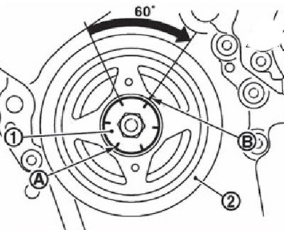
Make sure that the bolt is tightened to the required angle by the applied color mark.
Make sure the crankshaft rotates freely clockwise.
13. Install all remaining parts in the reverse order of removal.